TS 910 TRANSFER SWITCH
PM140 REV 2 14/01/23 44 Thomson Power Systems
To override momentary under frequency fluctuations, the under frequency
sensor is provided with a transient time delay period of 3 seconds which is non-
adjustable.
18.15 TSC 9 CONFIGURATION INSTRUCTIONS
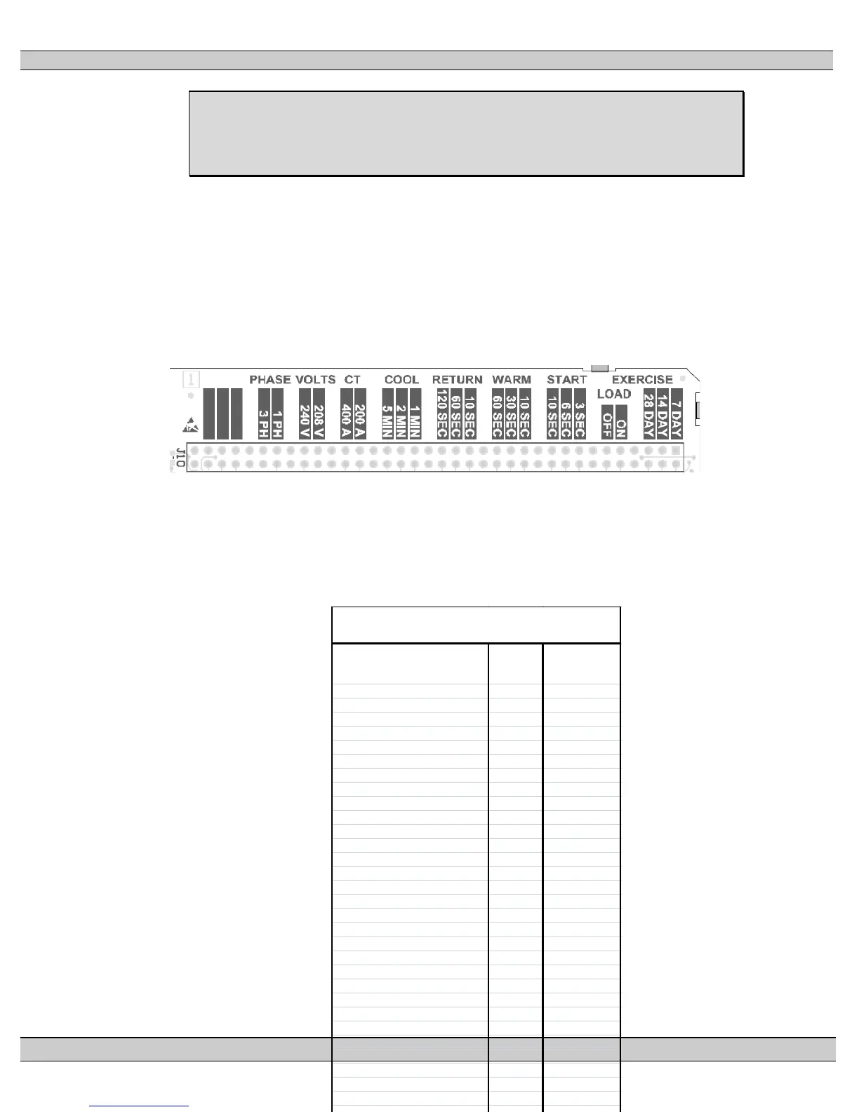
All user configuration of the TSC 9 controller is accomplished using hardware jumpers
located on top of the printed circuit board as per the following picture. No software
programming is required. The hardware jumpers are used for configuration of main
operating parameters such as system voltage, phases, and adjustable time delays.
18.15.1 FACTORY DEFAULT JUMPER SETTINGS
All TSC 9 configuration jumpers are set to default settings at the factory as per
the following table and should not require further setting.
EXERCISE TEST CY CLE
7 DAY
X
EXERCISE TEST CY CLE 14 DAY
EXERCISE TEST CY CLE
28 DAY
EXERCISE LOAD TRANSFER ON LOAD
EXERCISE LOAD TRANSFER OFF LOAD
X
ENGINE START DELAY 3 SEC
X
ENGINE START DELAY 6 SEC
ENGINE START DELAY 10 SEC
ENGINE WARMUP TIME
10 SEC
X
ENGINE WARMUP TIME 30 SEC
ENGINE WARMUP TIME 60 SEC
UTILTY RETURN DELAY 10 SEC
UTILTY RETURN DELAY 60 SEC
UTILTY RETURN DELAY 120 SEC
X
ENGINE COOLDOWN TIME 1 MIN
ENGINE COOLDOWN TIME 2 MIN
X
ENGINE COOLDOWN TIME 5 MIN
CURRENT TRANSFORMER SIZE 200A
CURRENT TRANSFORMER SIZE 400A
SYSTEM VOLTAGE 208V
X (3PH only)
SYSTEM VOLTAGE 240V
X (1PH only)
SYSTEM PHASE 1 Ph
X (1PH only)
SYSTEM PHASE 3 Ph
X (3PH only)
TSC 9
CONFIGURATION JUMPERS