TS 910 TRANSFER SWITCH
PM140 REV 2 14/01/23 57 Thomson Power Systems
24 APPENDIX A – TYPICAL AUTOMATIC TRANSFER SWITCH
COMMISSIONING PRIOCEDURES
a) PRE-ENERGIZATION CHECKS
1. Verify the generator and utility supply voltages are 120/240V (or 120/208V 3 Phase)
maximum.
2. Confirm power cable size is correct for the lugs supplied in the transfer switch (line, load,
and neutral) and are properly torqued.
3. Confirm transfer switch has been adequately grounded per NEC requirements.
4. Confirm power cables have been meggered to ensure no cross phase connections or
conduction to ground.
5. Check for mechanical damage.
6. Check no packaging materials or tools are left inside the transfer switch.
7. Verify control wiring connected to the pluggable terminal block is properly installed (i.e.
no frayed ends, screw are tight, no damage, etc).
8. Ensure TSC 9 Control Isolation Plug (J4) is inserted into the TSC 9 Controller prior to
operation.
9. Verify TSC 9 controller jumpers are set to reflect desired operation.
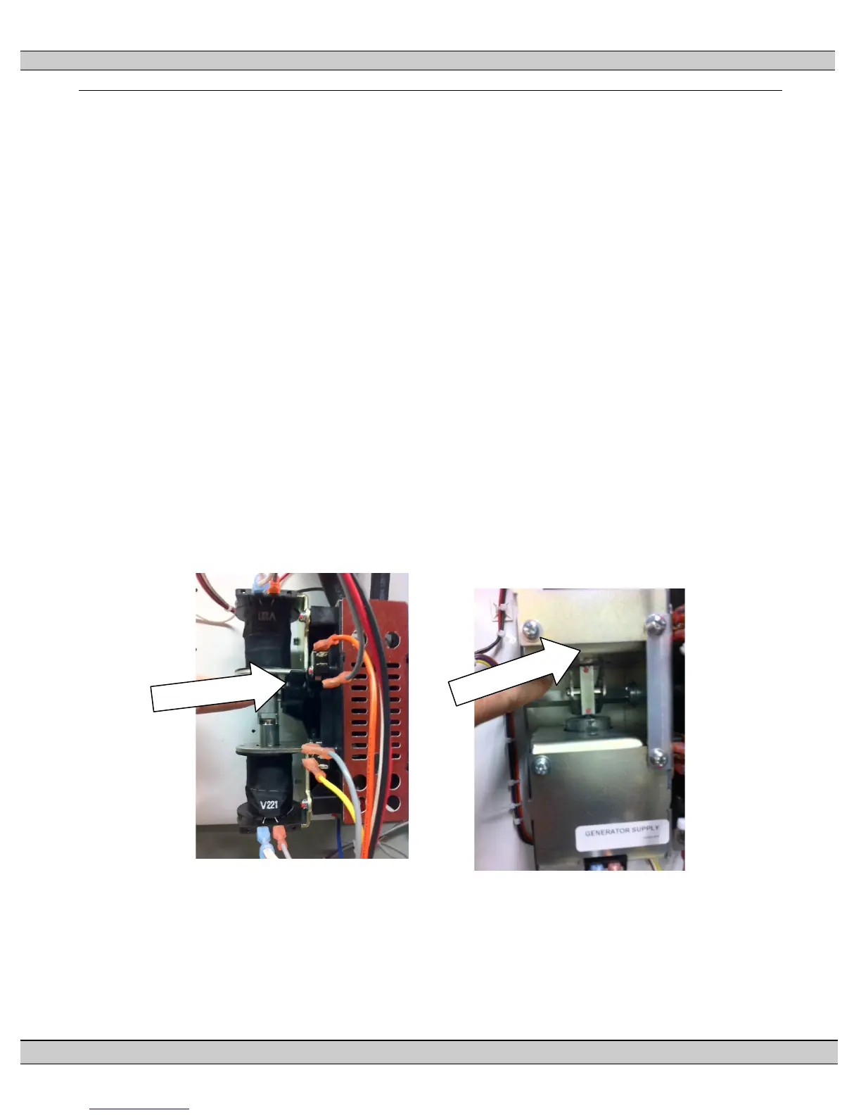
10. Visually verify the transfer switch power contactor is closed in the utility position. The
upper solenoid plungers will be pulled towards the upper coils (refer to photos below).
‘ 100A/200A Contactor Utility Position 400A Contactor Utility Position
11. Verify correct control wire interconnects have been installed to the generator set auto
start/stop controls. Note: The ATS Engine Start contact CLOSES to start the engine and
OPENS to stop the engine.
12. Ensure the inside of the transfer switch is clean from all dust, and other foreign
materials.
13. Re-install enclosure door front cover and tighten all cover mounting screws.