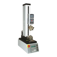
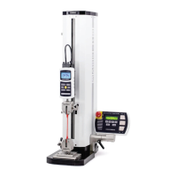
Model ESM301 / ESM301L Test Stand User’s Guide
20
1. Maintained (default)
The crosshead will move continuously once the button has been pressed. Subsequently
pressing STOP will stop crosshead motion.
2. Momentary
The crosshead will move only if the button is pressed and held. Releasing the button will
stop movement immediately.
3. Auto
Holding down the button for more than 0.5 seconds will enter Momentary mode, at which
time an audible indicator will sound and the LED indicator on the button pushed will be
illuminated. A short tap on the button will operate the test stand in Maintained mode.
Pressing STOP during Maintained mode will stop crosshead motion. To resume the test,
press UP or DOWN again.
Pressing EMERGENCY STOP will immediately stop crosshead motion in any mode. To release, rotate
clockwise. To resume the test, press UP or DOWN.
Crosshead movement will take place until a limit has been reached. If the crosshead has stopped at a
soft limit, the limit condition may be overridden by pressing and holding UP or DOWN for two seconds.
5.3.1 Travel Indication
If installed, travel indication is displayed in the upper left corner of the display. The displayed units are the
same as programmed in the UNITS feature. Indicated travel is a relative value. To zero the value, press
and hold STOP for two seconds.
If the cable connecting the crosshead to the rear of the controller is unplugged, the position value will not
change when the crosshead moves.
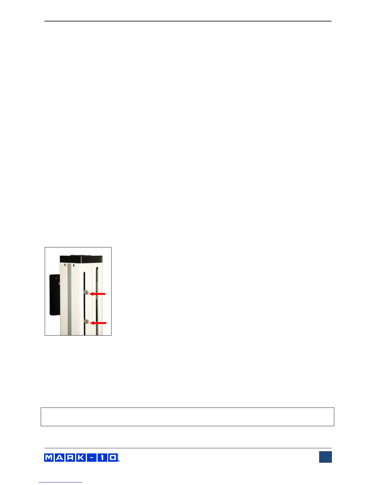
5.3.2 Limit Switch Operation
Limit switches allow the operator to set a location along the column at which
point the crosshead will stop moving. Limit switches are located at the rear of
the test stand column, as shown in the image to the left. Adjust the switches’
positions by loosening, repositioning, and re-tightening the thumb screws. The
thumb screws must be installed after unpacking. They are shipped separately
to avoid damage in transit.
5.3.3 Overload Protection
The 09-1162 cable is required for overload protection of a Mark-10 force gauge. If overload protection is
installed and enabled, the crosshead will stop when the programmed percentage of full scale of the force
gauge has been reached.
When overload protection is enabled, if the 09-1162 cable is disconnected, and/or if the force gauge is
turned off, an error message will appear. Plug in the cable and/or turn on the force gauge to clear the
message.
Note: When the crosshead is moving in the UP direction, only the tension overload setting is active.
When the crosshead is moving in the DOWN direction, only the compression overload setting is active.