Model WT3-201 Wire Crimp Pull Tester User’s Guide
4
3 SETUP
3.1 Mechanical Setup
3.1.1 Assembly
The lever is shipped disassembled from the unit to prevent damage in transit. To install, match the pin on
the cam mechanism with the corresponding blind hole in the lever hub. Then, tighten the plastic knob into
the threaded hole in the lever hub.
3.1.2 Mounting
Place the tester on a clean, flat and level work area free from vibration. If desired, the tester can be
secured to the work area with four 1/4-20 screws fastened into the underside of the base.
3.1.3 Sample setup
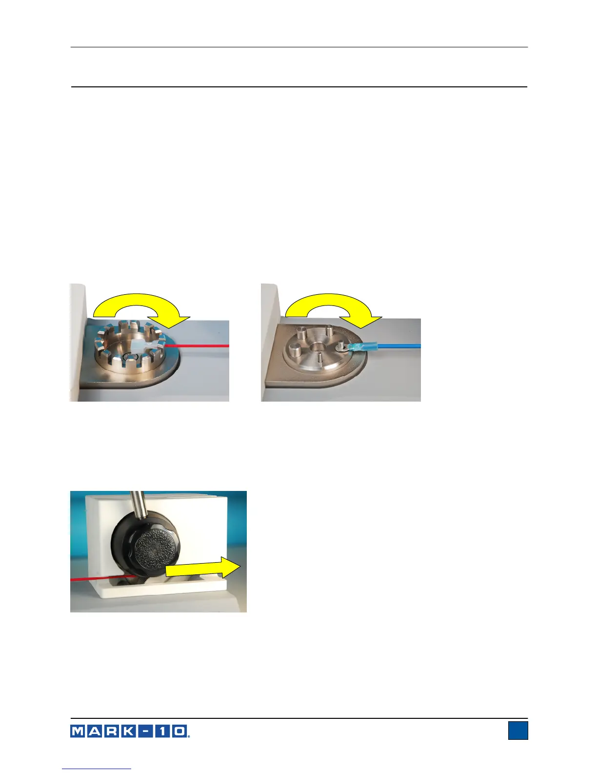
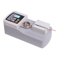
1. Secure the terminal into the standard terminal fixture or optional ring terminal fixture, as shown in
the figures below. Index the fixtures until the desired slot or ring size is aligned with the cam
mechanism adjacent to the lever. The fixtures will click when indexing to each size selection.
2. Rotate the lever clockwise until its end of travel.
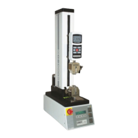
3. Insert the loose end of the wire between the cams in the mechanism adjacent to the lever, as
shown in the figure below. Keep the wire taut as it is inserted.
Fig. 3.1
Wire terminal fixture
Fig. 3.2
Ring terminal fixture (optional)
Fig. 3.3
Cam mechanism
www.GlobalTestSupply.com
Find Quality Products Online at: sales@GlobalTestSupply.com