Model WT3-201 Wire Crimp Pull Tester User’s Guide
6
4 HOME SCREEN AND CONTROLS
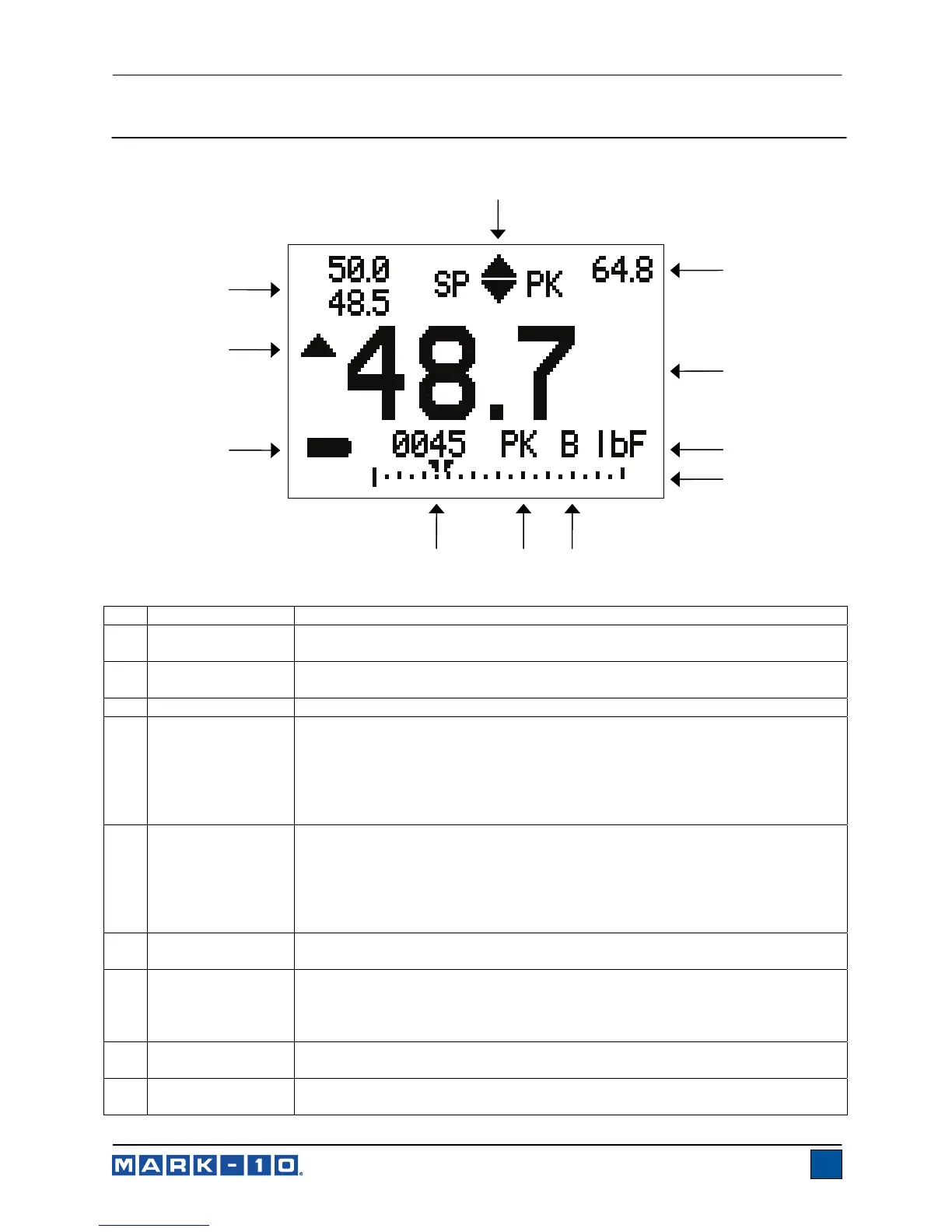
4.1 Home Screen
No. Name Description
1
Tension
indicator
This symbol indicates that a tension (pull) load is occurring. When this symbol
is not present, either no load is occurring, or a compression load is occurring.
2 Peak
The maximum measured tension force. This reading can be reset by pressing
ZERO or by powering the tester off and on.
3 Primary reading
The current displayed reading. See Operating Modes section for details.
4 Units
The current measurement unit. Abbreviations are as follows:
lbF – Pound-force
ozF – Ounce-force
kgF – Kilogram-force
N – Newton
kN – Kilonewton
5 Load bar
Analog indicator to help identify when an overload condition is imminent. The
bar increases from left to right, indicating increasing load. If set points are
enabled, triangular markers are displayed for visual convenience. This
indicator reflects the actual load, which may not correspond to the primary
reading (depends on operating mode). The ZERO key does not reset the load
bar. See Operating Modes section for details.
6
Break Detection
On/Off
The letter “B” appears if the Break Detection function is enabled. Refer to the
Break Detection section for details.
7 Mode
The current measurement mode. Abbreviations are as follows:
RT – Real Time
PK – Peak
See Operating Modes section for details about each of these modes
8
Number of stored
data points
The number of stored data points in memory, up to 1000. Displayed only if
Memory Storage is enabled for the DATA key.
9
Battery / AC
adapter indicator
Either the AC adapter icon or battery power icon will be shown, depending on
power conditions. Refer to the Power section for details.
1
2
3
5
78
9
10
11
4
6
www.GlobalTestSupply.com
Find Quality Products Online at: sales@GlobalTestSupply.com