Assembly
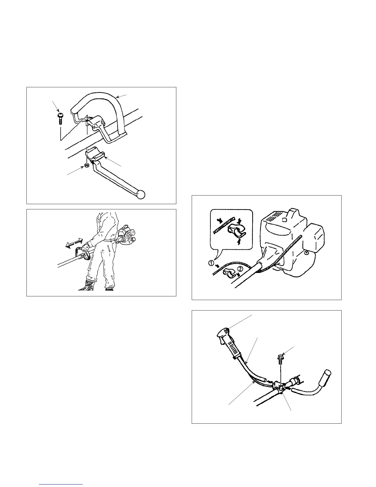
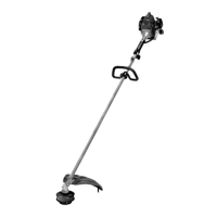
Loop Handle Installation
The loop handle kit contains a package of four screws
nuts and the bottom clamp for the loop handle.
1. Place the loop handle and the bottom clamp
approximately 9 inches (22.8 cm) from the end
of the stop switch/throttle trigger assembly for an
initial handle position.
2. Install the four screws and nuts. Leave the screws
finger-tight.
3. Reposition the loop handle up or down the drive
shaft to the most comfortable position, but no
closer than 9 inches (22.8 cm) from the end of the
stop switch.
4. Tighten the screws and nuts.
Handlebar Installation
IMPORTANT: Be careful not to damage the throttle
cable and stop switch wires when you remove the
horn handles from the carton.
1. Loosen the four screws on the top of the clamp
bracket.
2. Insert the left and right handlebar into the clamp
bracket. Note that the handlebar with the throttle
trigger and stop switch goes on the right-hand side
of the Trimmer/ brushcutter.
3. Adjust the handlebar to the desired position, then
tighten the four screws.
4. Clamp the throttle cable assembly as shown.
— US-11 —
Throttle Trigger and Stop Switch
Stop Switch Wires and
Throttle Cable
Clamp Bracket
Screw (4)
Handlebar
Loop Handle
Screw (4)
Nut (4)
Bottom Clamp