NomoLine ISA Service Manual Chapter 2: Maintenance Procedures
www.masimo.com 24 Masimo
Flow Accuracy Check
Setup
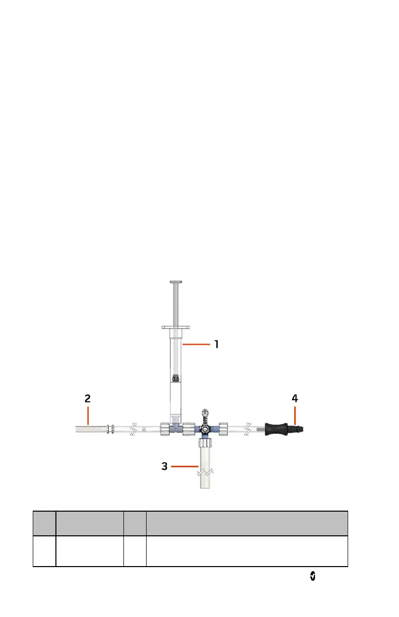
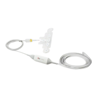
• Assemble the following components from the NomoLine ISA Maintenance Kit as
shown in figure 1-12. Refer to Maintenance Kit Components on page 14 for
component identification.
• Nomo connector with tubing (connects to the NomoLine ISA system Input
Connector)
• Flow-check device with silicone tubing (leave disconnected)
• Syringe
• Tubing with ID 4.0 mm (5/32”) (connects to handheld digital manometer)
• 4-way stopcock lever set in the position shown
• 3-way connector
• HM28 Handheld digital manometer.
Figure 1-12
Item Description Item
Description
1 Syringe 3 Connect to the handheld digital manometer with
appropriate tubing.