NomoLine ISA Service Manual Chapter 2: Maintenance Procedures
www.masimo.com 25 Masimo
Item
Description Item Description
2 Leave
disconnected
4 Connect to the ISA Input Connector.*
* See NomoLine ISA CO2/AX+ Interface on page 11 or ISA OR+ Interface on page 12.
Procedure
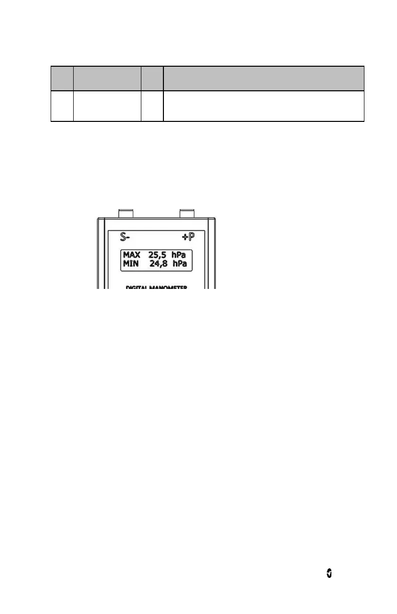
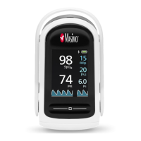
1. Configure the HM28 device to display measurement values in hPa.
2. Press "MODE" button until the display shows MAX/MIN values as in figure 1-13.
Figure 1-13
3. Make sure the NomoLine ISA system is powered ON.
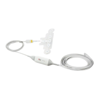
4. Connect the NomoLine ISA Maintenance Kit to the NomoLine ISA Input Connector
shown in figure 1-12 and leave the exhaust open. See NomoLine ISA CO2/AX+
Interface on page 11 or ISA OR+ Interface on page 12.
Note: Verify the 4-way stopcock lever position in figure 1-12.
5. Press "CLEAR/ZERO" button on the HM28 digital manometer.
6. Wait for 30 seconds.
7. Calculate a mean value based on the MAX/MIN values displayed on the HM28
digital manometer.
Test result:
The NomoLine ISA system sampling flow rate
1
is inside specified range if the mean value is
within specified acceptance criteria
2
. The NomoLine ISA system should not be used if it fails
to meet the acceptance criteria limits.
1
Sampling flow rate: 50± 10 sml/min
2
Acceptance criteria: 16 to 24 hPa
Gas Span Check
Overview
The gas span check procedure requires the use of a suitable calibration gas mixture. A
cylinder containing such mixture may be acquired from the vendor of your choice, provided
the following gas concentrations and accuracy are met.