TheSantaFe(flueless)modelsuseaflexiblehoseandbayonet.Thebayonetcanbeconnectedtoan
AGAapprovedG1/2”floorbayonetsocket.
Inallcasesashut-offvalveshouldbeinstalleddirectlybehindtheheatertofacilitateisolationofthe
heaterforservicing.
Itisessentialtopurgeallgaslinesbeforemakingtheconnectiontotheheatertoeliminateanyswarf.
Donotmaketheconnectionuntilthesuitabilityofthefluepositionhasbeenconfirmed.
GASPRESSUREADJUSTMENT.
Allpressureadjustmentsmustbemadewhiletheheateris
operatingonthe‘HIGH’setting.
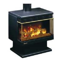
BOSTONANDODESSANG.Thesehaveapressureregulatorseparatefromthecontrolvalve.The
regulatormustbesetto1.0kPa.Thepressuretestpoint isonthesideoftheregulatorandthe
adjustingscrewisonthetop.Slackenthelock-nutandrotatethescrewbyhand,screwingdownto
increasethepressure.Tightenthelocknutafteradjusting.
BOSTONANDODESSALP.Thesemodelshavenointernalpressureregulatorastheyrundirectlyon
the2.71kPapressuredeliveredbythegasbottleregulator.
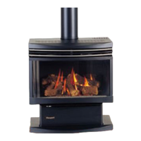
SANTAFENG.Thesehaveapressureregulatorbuiltintothecontrolvalve.Thepressuretestpointis
thetoponeontheendofthecontrolvalvefurthestfromthegasinlet.Pressureadjustmentsare
madewiththesmallslottedscrewaboveandslightlytotherightof thegasinletonthecontrol
valve.Adjustto0.9kPa.
SANTAFELP.Thereisnopressureregulatorinthecontrolvalve.Thecorrectpressureof2.71kPa
should bedelivered bythegas bottle regulator. Thetest point for checking this pressure is the
uppermostoneontheendoftheappliancevalvefurthestfromthegasinlet.
ELECTRICITY. Plug the fan lead into a 230 volt power outlet and check that the fan operates
correctlyonallspeeds. Thefan switchisunder thelid (on the cabinet top) which covers the gas
controls.
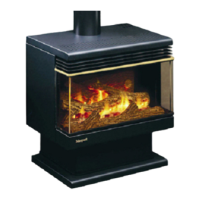
FLUE(ForBostonandOdessamodels)
USEONLYANAPPROVEDFLUESYSTEM.
1. Stand theheater in its proposed position, taking care to observe the minimum clearances
shownonpage3.Theheaterdoesnotrequireahearthorfloorprotector.
2.Dropaplumb-bobfromtheceilingtohangcentrallyinthefluesocketoftheheaterandmark
thepositionontheceiling.Driveasmallnailthroughatthispointandinspecttheceilingand
roof to ensure that the flue and its trim will be at least 25mm clear of any combustible
material. The flueterminationrequirementsstatedin ‘Positioning theHeater’ (page2)will
alsoneedtobemet.
3.Cutappropriateholesthroughtheceilingandroofmaterialandinstalltheflueinaccordance
withtheinstructionsaccompanyingit,takingcaretoprovideanysafetyclearancesspecifiedin
theinstructions(usually25mmbetweentheflueshieldandanynearbycombustiblematerial).
TheinstallationmustmeettherequirementsofAG601orNZS5261asappropriate.Thetop
ofthefluemustbeabovetheroof,atleast500mmclearofanypartoftheroofandatleast1
metrehorizontallyfromanyneighbouringstructure.Allfluesectionsmustbesecurelycoupled
toeachother.
5.Flashtheupperflueatthepointofexitthroughtheroof,topreventwaterentry,andfitthe
fluecap.
It is the responsibility of the installer to ensure that the flue system is operating
correctly.See‘TESTFIRING’below.
4
 Loading...