SERVICINGINSTRUCTIONS
Servicingmustbecarriedoutonlybyauthorisedpersonnel.
Minor adjustmentscanbemade withtheheaterinitsnormaloperatingposition,but it will be
foundmoreconvenienttomovetheheaterawayfromthewallformajorwork.
Ifitisnecessarytomovetheheater:-
•Shutoffthegassupplyatthevalvebehindtheheater.
•Removetheaccessplateontherearofthecabinet.
•Disconnectthegaslineattheheater.
BostonandOdessa(flued)modelsonly
•Liftthefluetrimabout75mmandsupportitwithawoodenblock.
•Slackenanyflueclamp,andliftthefluewhilemovingtheheaterfrombeneathit.
•Slidetheheaterawayfromthewall,supportingtheflueandtrimonasuitablespacer.
Allmodels
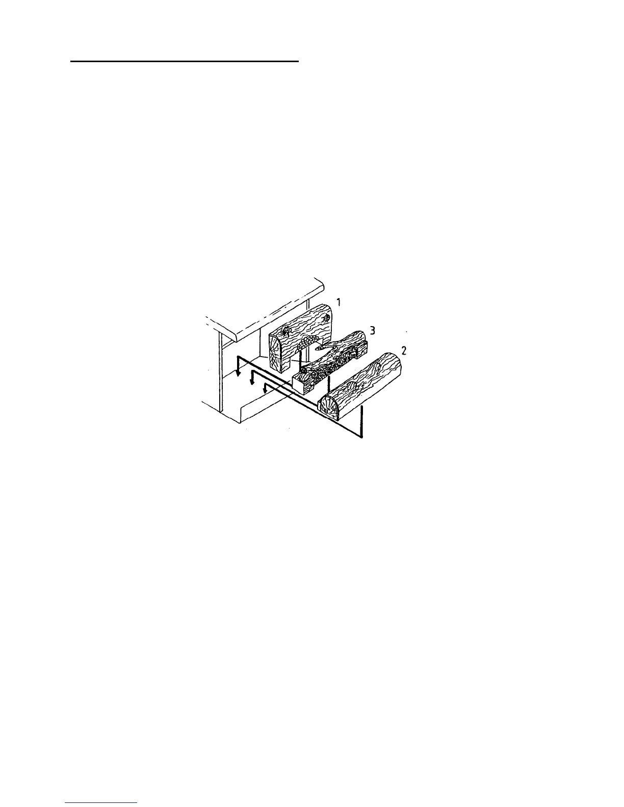
• Keep the heater upright at all times to avoid displacing the logs. The correct gas-log
positionsareshownbelow.
ACCESSPOINTS
1.Thecabinetrearandsidecoverplates.Thesegiveaccesstothegasentryconnection,thepressure
regulatorandthegascontrolvalve(incorporatingthepiezoignitermodule).OntheBostonand
Odessamodelsthefilterforthepilotlightgassupplyisunderthelargecheese-headedscrewon
topofthegascontrolvalve.
2.Thefanassembly.Removalgivesaccesstothemainburnergasconnectionandinjector.The
correctinjectorsizeforeachgasisspecifiedonthedataplateonachainattherearofthecabinet.
Themainburneraerationisnotadjustable.
3.Theglass.Seebelowforremovalinstructions.Accessisthenavailableforthelogassembly,the
pilotlight,igniterpointsandflamesafetysensorandthemainburner.
4.Theentireuppercabinetmayberemovedifaccesstotheheatexchangerisnecessary.First
removetheglass.Thecabinetisretainedbyeightscrewsfromunderneathandthreescrewson
eachfrontverticaledgeofthefirebox.
GLASSREMOVALANDASSEMBLY
Carryouttheseproceduresonlywhiletheheaterisstandingupright.
1.Removethelouvrebyliftingitupwardsandoutwards.
2.Removesixfasteningscrews(Odessa,fourscrews)securingthetopglasstrim.
3.Liftthetopglasstrimclear.Note.OntheBostonandSantaFemodels,thiswillreleasethetop
edgesofthethreeglasspieces.Ensurethattheydonotdropout.
7
 Loading...