Making Measurements
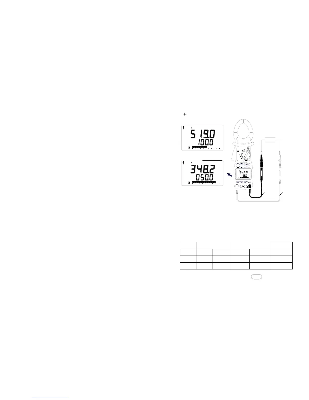
Measuring AC Voltage
( Figure 3. Voltage Measurements)
1. Turn the selector to one of Φ1,Φ2,Φ3, refer to Table 3 to connect
the test leads to input terminals: Insert the black test lead into the
COM input terminal and one corresponding color test lead into the
corresponding input terminal.( Figure 3 )
(Table 3 Input Terminal Connections)
SELECTOR INPUT TERMINAL(+) INPUT TERMINAL(-) Phase
Φ1 V1 jack Yellow lead COM jack Black lead First phase
Φ2 V2 jack Green lead COM jack Black lead Second phase
Φ3 V3 jack Red lead COM jack Black lead Third phase
2. Connect test leads to the load, press
V / Hz
button, voltage
measured value is displayed in the primary display and current
frequency value of voltage is shown in the secondary display.
- 11 -
V
AC
MEM
302010
0
FREQ
FREQ
MEM
AC
1
20 40 60 80
0
40
V1
V3
V2
MIN
COM
SAVE
MAX
AUTO RANGE
Ture RMS
AC
kW / PF
V / Hz
100
Hz
Hz
V
MAX
600kW
1000A
MEM
1
-
OFF
P
2
1
OFF
HOLD
V
Hz
MAX
IICAT.I
600V
kWh
TIME
RS232
CLEAR
10 20 30 40
W
FREQ
3
0
MR
EX
kVA
kVAr
A
Yellow
Black
V1
V
AC
Circuit
1