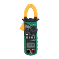
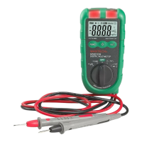
5. Input terminal
V1: The input terminal for the first phase, using the yellow test lead
to connect.
V2: The input terminal for the second phase, using the green test
lead to connect.
V3: The input terminal for the third phase, using the red test lead to
connect.
COM: Common terminal, the earth input terminal for all measure-
-ment modes, using the black test lead to connect.
6. LCD Display
4 digits display, 7 segment LCD to display function mode, measured
value and symbols.
7. Trigger
Press the lever to open the transformer. When the lever is released,
the jaws will close again.
8. RS232C Data Interface
Your clamp meter can use a serial interface cable to communicate
with a computer. Refer to Figure 18 for complete instructions.
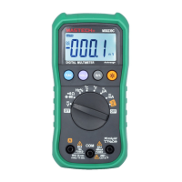
Using the Selector
Turn the meter on by rotating the selector to any function as following .
( Table 1. Introducing The Selector)
ITEM DESCRIPTION
POWER OFF. Turn the meter off OFF
EX- P EXTERNAL POWER SUPPLY. No use battery, select tested
voltage signal be power supply for Active Energy measure-
-ment for long at one time.
RECALL DATA. Recall saved data in the meter memory. MR
TOTAL POWER. For display total power value of three phase ∑W
– 5 –