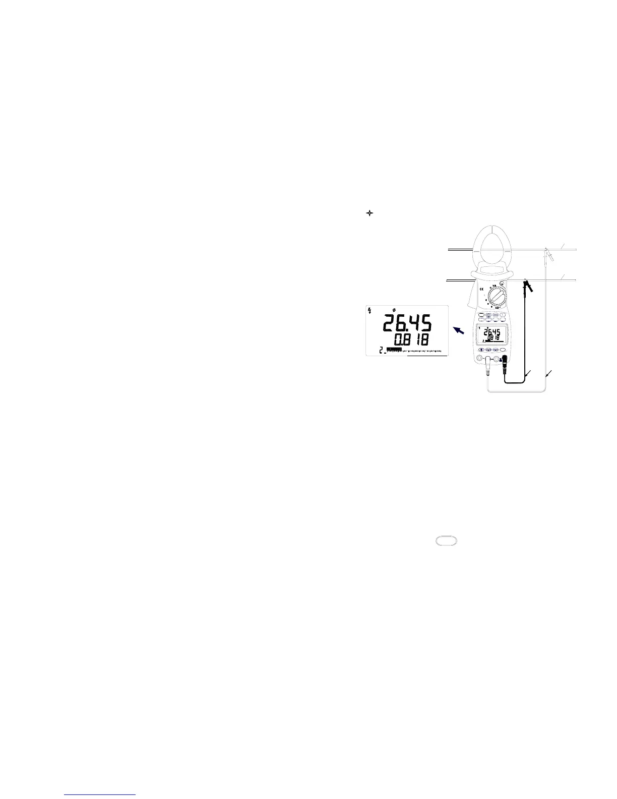
Measuring Single-Phase Circuit
(
Figure 8. Single-phase Power Measurements)
1. Hook the clamp jaws around the conductor of the loading or the
circuit. The clamped conductor is one phase which you want to
test in the three-phase circuit.
2. Turn the selector to one of Φ1,Φ2,Φ3, and refer to Table 3 to
connect test leads into input terminals which is corresponding to
the position of the selector. ( Figure 8)
3. After right connection, you can measure five power parameters of
single-phase circuit (Active Power, Power Factor, Apparent Power,
Reactive Power, Active Energy):
( 1. ) Active Power(kW) and Power Factor (PF) (Figure 8 )
a. Press
kW / PF
button, the Active Power value is shown in
the primary display and the Power Factor value, “PF”
symbol are shown in the secondary display. When the
Power Factor value is negative, the loading is capacitive.
- 15 -
2
00
MEM
PF
20
AC
kW
40 60 80 100
kWh
TIME
kVA
kVAr
kW / PF
MIN
6040
V2
2
MAX
20
V1
PF
AC
MEM
00
V3
V / Hz
A
RS232
Black
COM
SAVE
10080
kW
CLEAR
Green
Tested conductor
1
OFF
OFF
2
EX
3
-
P
AUTO RANGE
W
MR
Ture RMS
MAX
600kW
1000A
HOLD
MAX
IICAT.I
600V
Earth wire