Masterflex
Section 3
Operation
MASTERFLEX
®
Digital Pump Drive Operating Manual 3-21
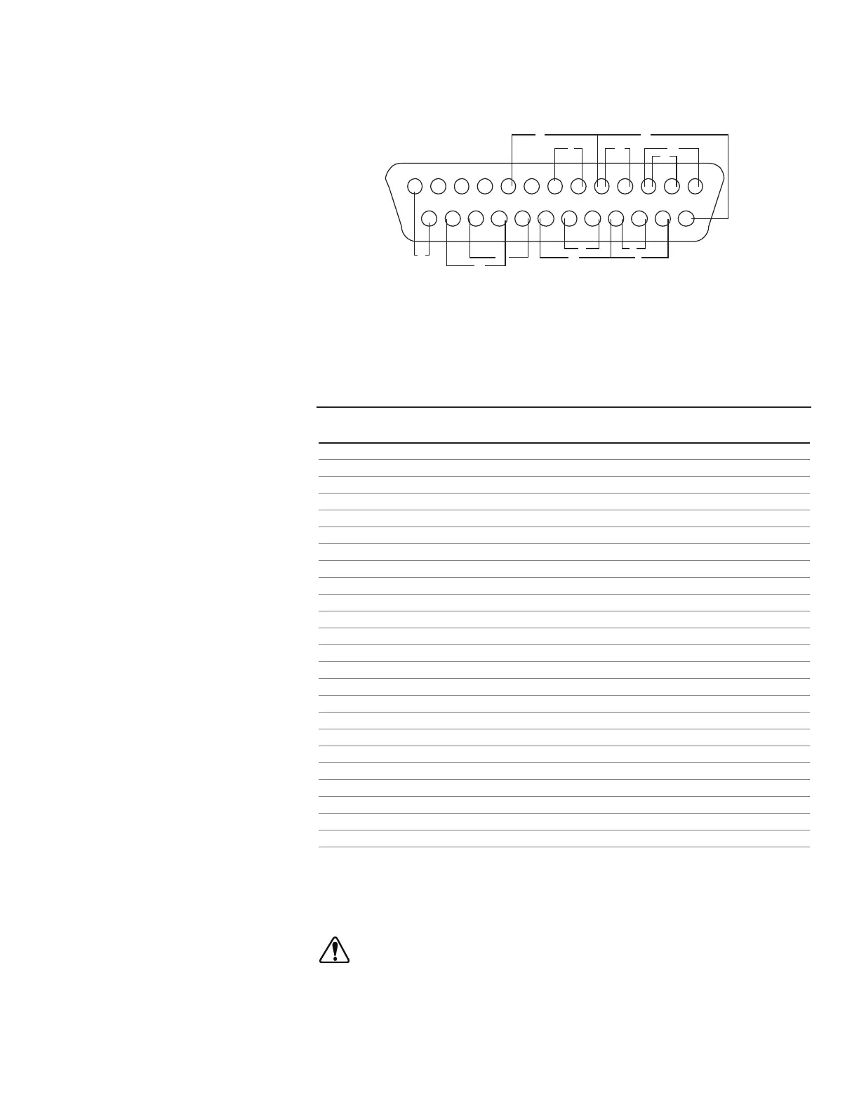
DB-25 Pin
Configuration with
Wiring Scheme
Contact Arrangements
CAUTION: Power must be turned off before connecting the
external remote control cable to prevent damage to the drive.
NOTE: Open collector outputs in "low impedance" state are at earth
ground and when in "high impedance" state are essentially floating. See
Open Collector page 3-24.
Figure 3-10. DB-25 Pin Configuration with Wiring Scheme.
A. START/STOP
B. CW/CCW
C. OUTPUT 0-20mA; 4-20mA
D. INPUT 0-20mA; 4-20mA
E. INPUT 0-10V
F. OUTPUT 0-10V
G. TACH OUTPUT
H. PRIME
I. MOTOR RUNNING N.O. (1A @ 24V)
J. LOCAL/REMOTE ENABLE
K. 24V (150mA max.)
L. General Alarm N.O. (1A @ 24V)
M. Local/Remote Indicator (LOCAL N.O.)
Pin No. Description
DB-25
1 Speed Control Voltage Input (0-10V)
2 Speed Control Current Input (0-20 mA)
3 Speed Control Input Ground Return
4 Speed Signal Current Output (0-20 mA)
5 Speed Signal Output Ground Reference
6 Motor Running Relay (N.O.)
7 Motor Running, Relay Common
8 Reserved – Not Used
14 Speed Signal Voltage Output (0-10V)
15 Remote Start/Stop Input
16 Remote CW/CCW Input
17 Remote Start/Stop, CW/CCW, Prime, Local/Remote Grnd Ref.
18 Tach Ground Reference
19 Tach Output (open collector)
20 Remote Prime Input
9 Remote Voltage or Current Enabled
10 Reserved – Not Used
11 Reserved – Not Used
12 Reserved – Not Used
21 General Alarm Relay Common
22 Local/Remote Indicator Relay Common
23 General Alarm Relay
24 Local/Remote Indicator Relay
25 Aux 24V + (150 mA)
13 Aux 24V - (150 mA)
NOTE: Pins 5, 13, 17, and 18 are at earth ground, all are suitable for use
with START/STOP, PRIME, Direction, Tach, LOCAL/REMOTE,
Current and Voltage Outputs.