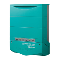
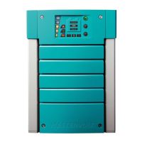
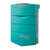
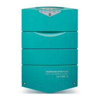
ChargeMaster Plus 12/35-3, 12/50-3, 24/20-3, 24/30-3 – User and Installation Manual
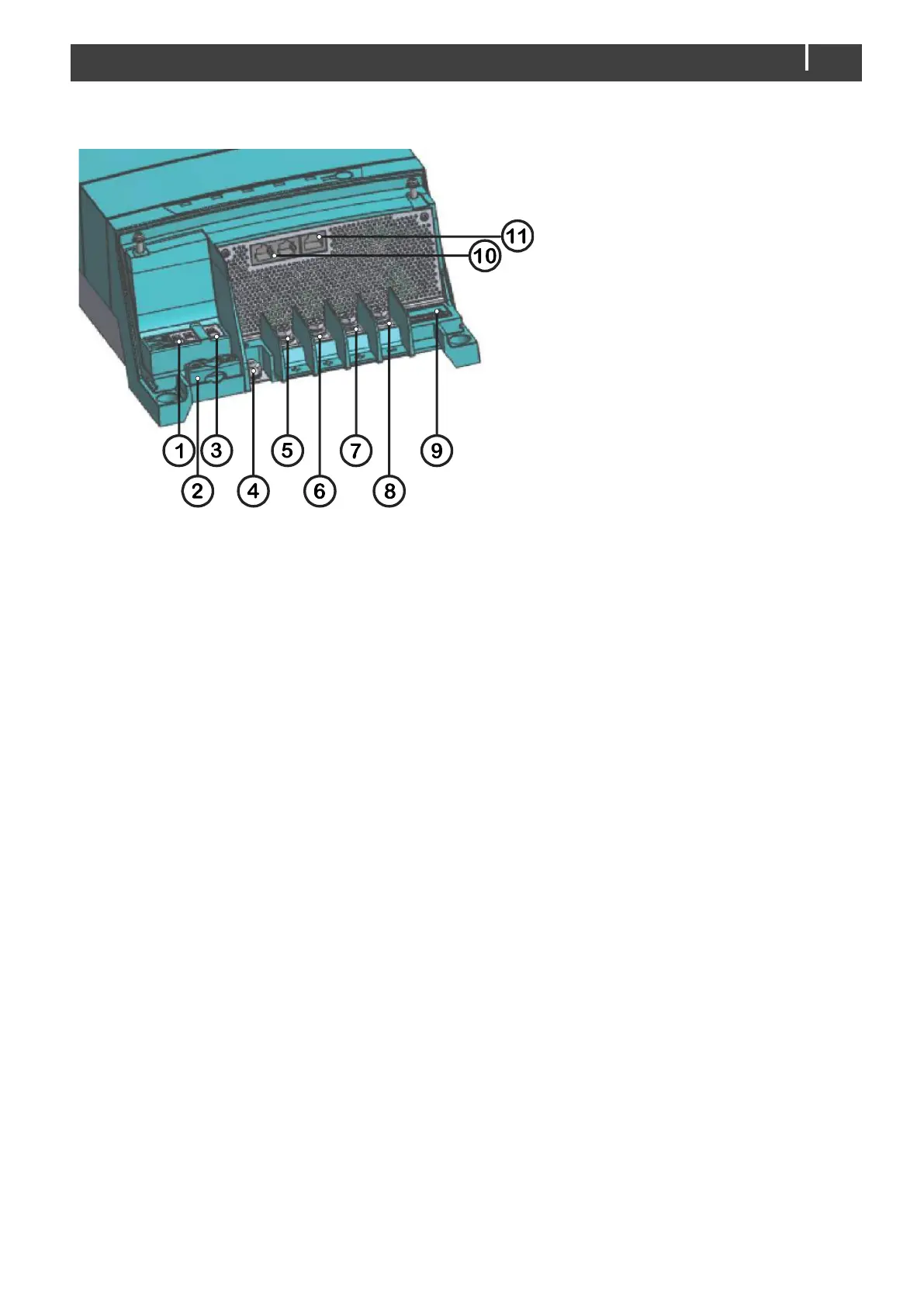
1. Spring cage terminal AC input
2. Strain relief for AC wiring (M3)
3. Safety ground connection 1*
4. Safety ground connection 2*
5. M6 Positive terminal charge output
1; DC 1 OUT
6. M6 Positive terminal charge output
2; DC 2 OUT
7. M6 Positive terminal charge output
3; DC 3 OUT
8. Common negative output terminal
9. DIP switches
10. Network connection
(CZone/MasterBus)
11. Temperature sensor connection