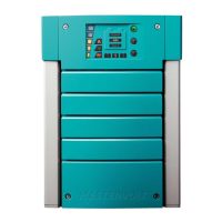
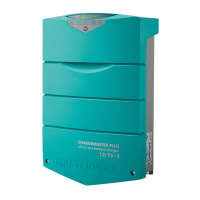
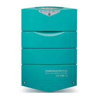
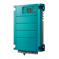
ChargeMaster Plus 12/35-3, 12/50-3, 24/20-3, 24/30-3 – User and Installation Manual
4.2.4 Configuration settings
The configuration can be done in MasterAdjust, from a laptop or notebook connected to the
ChargeMaster Plus via a Mastervolt USB Interface. See applicable user manuals for details. The following
table lists the parameters as shown in MasterAdjust.
Notes: - DIP switch settings overrule MasterBus settings. If DIP switches are not in their default setting,
the corresponding MasterBus setting is grayed out.
- To be able to make changes to the configuration via MasterBus, DIP switch 1 must be in the
ON position.
Menu language of this device
EN, NL, DE, FR, ES, IT,
NO, SV, FI, DA
Name of this device. This name will be
recognized by all devices connected to
the network
If Powersave mode is ON, the charger
will switch itself off when no AC power
is available.
If Powersave mode is OFF, the charger
stays ON even when no AC power is
available.
This checkbox is marked when the
ChargeMaster Plus is setup to work in a
CZone network
3-Step+, constant
voltage
Maximum DC output current
Depending on model
20-100%
The battery type settings are based on
Mastervolt batteries. If connecting
batteries of a different manufacturer,
make sure the manufacturer's recom-
mendations are met. Should this not be
the case, then "User defined" must be
selected to change the settings.
User defined, AGM,
Gel, Flooded, Lithium-
ion (MLI)
Temperature depended charge voltage
compensation
Bulk voltage (@ 25°C); see section 5.4
Minimum time of the Bulk phase since
Start bulk timer
Battery voltage trigger point to start the
bulk timer
Maximum time of the Bulk phase since
Start bulk timer