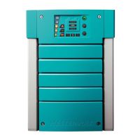
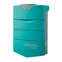
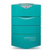
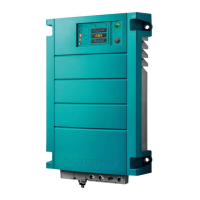
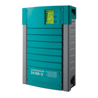
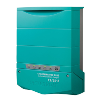
ChargeMaster Plus 12/35-3, 12/50-3, 24/20-3, 24/30-3 – User and Installation Manual
Use the following wire colors for DC wiring color
or at least different colors to make a clear
distinction between the positive and negative
wire from the battery:
Run the positive and negative cables next to
each other to limit the electromagnetic field
around the cables. The negative cable should be
connected directly to the negative post of the
battery bank or the ground side of a current
shunt. Do not use the chassis frame as the
negative conductor. Tighten securely. The
positive battery cable must be fused and
connected to the positive post of the battery
bank.
The recommended DC fuses for DC 1/2/3 OUT
are:
The fuse with the fuse-holder is available from
your local Mastervolt distributor or Customer
Service Representative.
3.3.2 AC wiring
WARNING!
On first connecting to power,
make sure the ChargeMaster
Plus is in a well-ventilated area as
it might spark.
For a safe installation the correct wire cross
section must be applied. Don’t use a cross
section that is smaller than indicated. See the
following table to select the appropriate cross
section for the AC wiring (up to 6m / 20ft length):
Connection of AC wiring and recommended wire
colors:
• 240VAC, 50/60Hz installations:
• 120VAC, 50/60Hz installations (single phase):
• 240VAC, 50/60Hz (split phase 120/240VAC):
Note: An accessible disconnection device
(switch or circuit breaker for example)
must be incorporated in the AC wiring, in
accordance with wiring rules.
3.3.3 AC safety grounding
WARNING!
The ground wire offers protection
only if the enclosure of the
ChargeMaster Plus is connected
to the safety ground. Connect the
ground terminal (PE / GND) to the
hull, chassis or Distribution
Apparatus.
CAUTION!
According to local regulations an
RCD/Breaker (also known as
GFCI) must be placed in the AC
input circuit of the ChargeMaster
Plus.
For Australia and New Zealand, the
wiring rules are in accordance with
AS/NZS 3000.