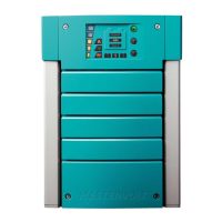
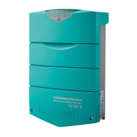
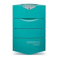
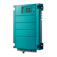
ChargeMaster Plus 12/35-3, 12/50-3, 24/20-3, 24/30-3 – User and Installation Manual
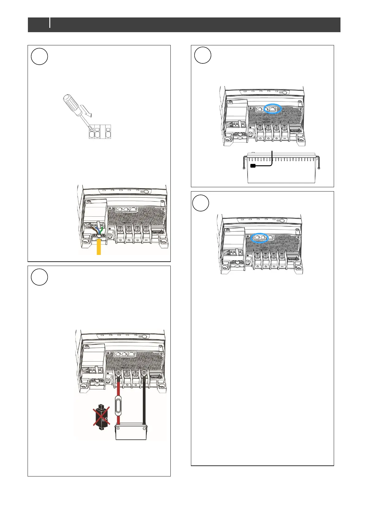
Connect the AC wiring to the spring-
clamp terminals:
1 Push a flat-blade screwdriver
(3mm / 1/8") into the square hole
to open the related wire port.
2 Insert the wire 15mm / 0.6" into
the opening.
3 Remove the screwdriver.
Fasten the cable with the strain relief.
Integrate a fuse holder in the positive
battery wire but do not place the fuse
yet!
Fit crimp-on cable lugs to the DC
cables. Connect the DC cabling of
battery bank 1, positive to +, negative
Tightening torque: 4.9 – 5.4 Nm
Repeat steps for output 2 and 3.
Attach the battery temperature sensor
to the casing of battery bank 1.
Plug the temperature sensor cable
into the “Temp sense” jack.
Option: Connect the ChargeMaster to
the CZone or MasterBus network.
Adding to a CZone network
1 Disconnect the backbone at the
closest backbone connection and
add in a tee connector.
2 Reconnect the backbone
connection(s) with the new tee
connector in place.
3 Connect the RJ45 CZone/MB drop
cable to the black coupler on the tee
and then connect to the
ChargeMaster Plus. Plug the
connectors into either of the ports.
Adding to a MasterBus network
1 Disconnect a MasterBus cable or
Terminator from the closest
MasterBus device and connect it to
the ChargeMaster Plus.
2 Connect the new MasterBus cable to
the other MasterBus device and then
connect to the ChargeMaster Plus.
Ensure that the network is properly
terminated.
 Loading...