MPPT Solar ChargeMaster 25 – User and Installation Manual
4.7.2 Installation step by step
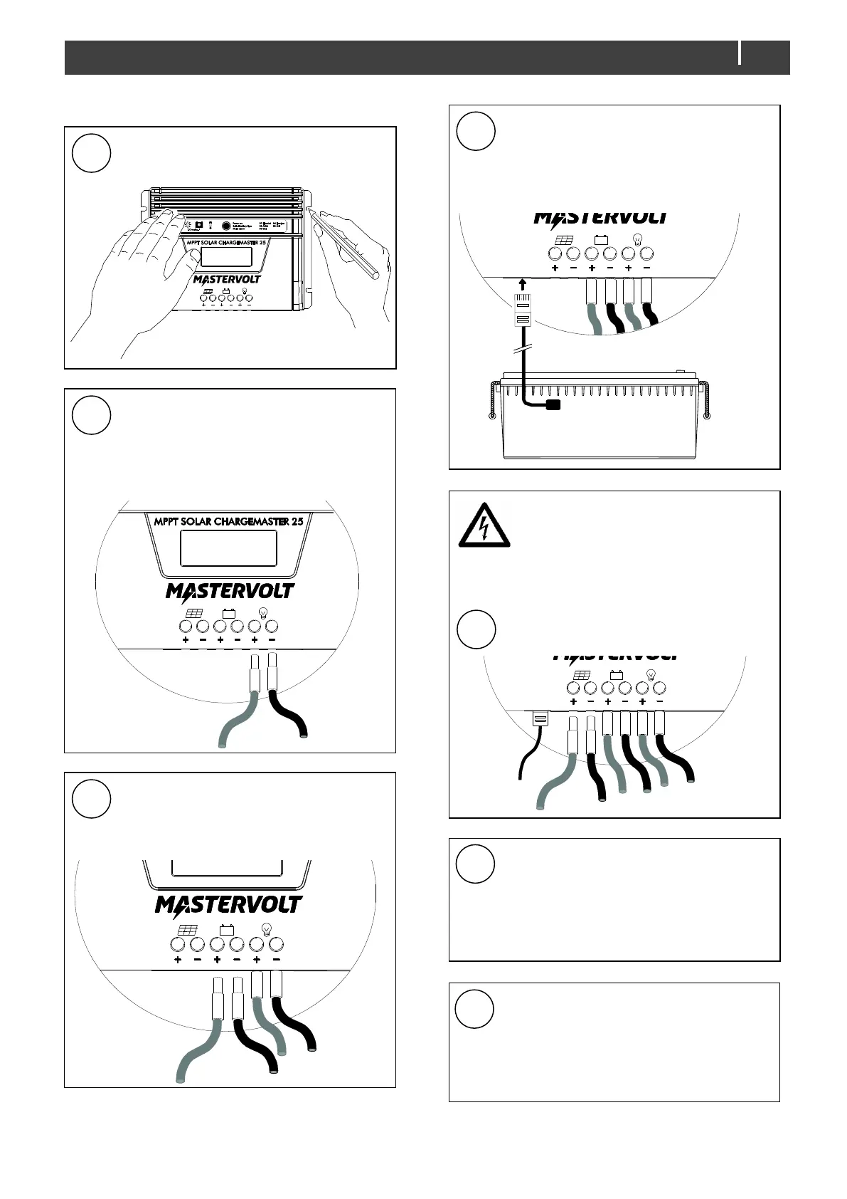
Mark the position of the four mounting spots.
Then fix the casing to the wall.
Fit boot lace ferrules to all DC-cables.
Connect the wiring of the Load-output (see
section 4.5). Integrate a fuse holder in the
positive load wire, but do not place the fuse
yet.
Connect the wiring to the battery.
Integrate a fuse holder in the positive battery
wire, but do not place the fuse yet.
Attach the battery temperature sensor to the
casing the battery.
Plug the temperature sensor cable into the
Temperature sensor jack.
Risk of shock! When the PV array is
exposed to light, it supplies a dangerous
DC voltage. See section 4.4.
If grounding is required, connect the
grounding terminal to the central grounding
point of the electrical installation; see Figure
1, item 10.
See also section 4.7.1
Check all wiring: positive to +, negative to –.
See also Figures 6 and 7 for wiring
examples.
If OK, continue with section 4.8 for
commissioning of the Solar ChargeMaster.

 Loading...