The Solar ChargeMaster can be used with any PV array
configuration that satisfies the following requirements:
• Maximum open circuit PV voltage: 75 V DC;
• The open circuit voltage from the PV array must be
5Volts higher than the battery voltage.
Note: The Solar ChargeMaster will automatically limit the
input current and power to its specified rating (see
section 6.1). Excess power will not be converted.
4.5 CONNECTION OF LOADS
Depending on the energy system in which the Solar
ChargeMaster is used, there are two options to connect the
electrical load to the Solar ChargeMaster:
• To the Load output on the Solar ChargeMaster, or
• Directly to the battery.
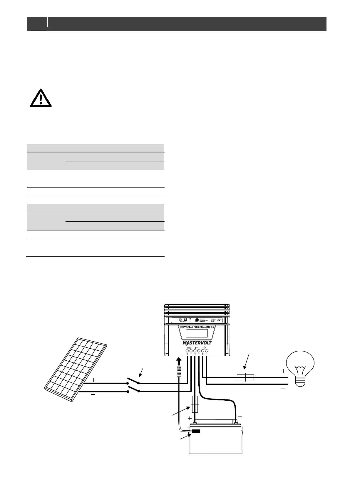
4.5.1 Load connected to the Load output
See Figure 6 for a typical installation diagram. The Load
output is provided with a protection circuit that switches off
the connected load automatically in case of overload or if
the battery voltage is too low. This kind of installation is
typically used when the PV-modules are the only source of
electrical power to charge the battery.
Characteristics:
• Maximum DC-load: 25A
• Under voltage disconnect: 10.5V
• Under voltage reconnect: 11.0V
4.5.2 Load connected to the battery
If the maximum load will exceed 25 Amps or if the battery
will also be charged by other energy sources, such as a
battery charger or an alternator, the electrical load shall be
connected to the battery directly. See Figure 7 for a typical
installation diagram. In this situation the battery is no longer
protected against too low battery voltages. Installation of
additional undervoltage protection circuits may be
necessary.
Figure 6: Load connected to the Load output on the Solar ChargeMaster

 Loading...