MPPT Solar ChargeMaster 25 – User and Installation Manual
3.4 OVERVIEW
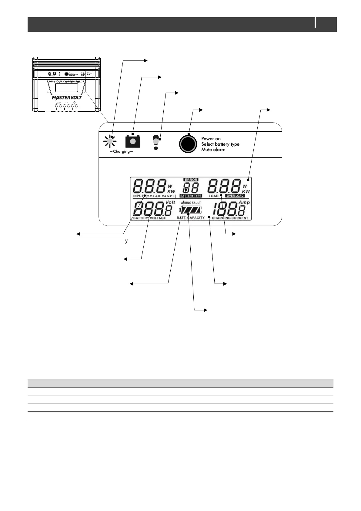
Figure 5: Operation of the Solar ChargeMaster
3.5 POWER SWITCH
Activate LCD-display (see text below)
Switch on Solar ChargeMaster again after a fault or error situation
Battery type setting, see section 4.8.2
Actual input power from PV-array
(Watts)
Battery type setting;
see section 4.8.2
ERROR
An error code is displayed in case
of a fault condition
Actual output current of the Battery
Output (Amps)
Actual load connected to the Load
Output (Watt)
OVERLOAD
Highlighted or blinking in case of
overload
POWER switch
See section 3.5
Actual battery voltage (Volts)
Estimation of the battery state of charge;
WIRING FAULT
Highlighted in case of error in the wiring;
Fault indicator LED
A fault condition is detected; see section 3.6
Charge indicator LED
The batteries are being charged; see section 3.6
Solar indicator LED
PV Power is available; see section 3.6

 Loading...