17.3 Working with pulse start events 123
17.3 Working with pulse start events
The pulse start configuration list represents a Hardware Real-Time Controller (HRTC) as known from
USB 2.0 camera mvBlueFOX. The mvHYPERION features two HRTC's (PulseStartConfiguration0 and PulseStart←-
Configuration1). A HRTC generates signals at the digital outputs, which can be defined by the user.
Currently you can use the HRTC in three ways:
• Periodical repeat of the pulse sequence
– parameters :
*
frequency of the pulse sequence [Hz]
• Single run through
– parameters :
*
digital input or on-board signal, which starts the pulse sequence initially -> "DigitalSignal"
*
falling or rising edge of the digital input -> "TriggerMoment"
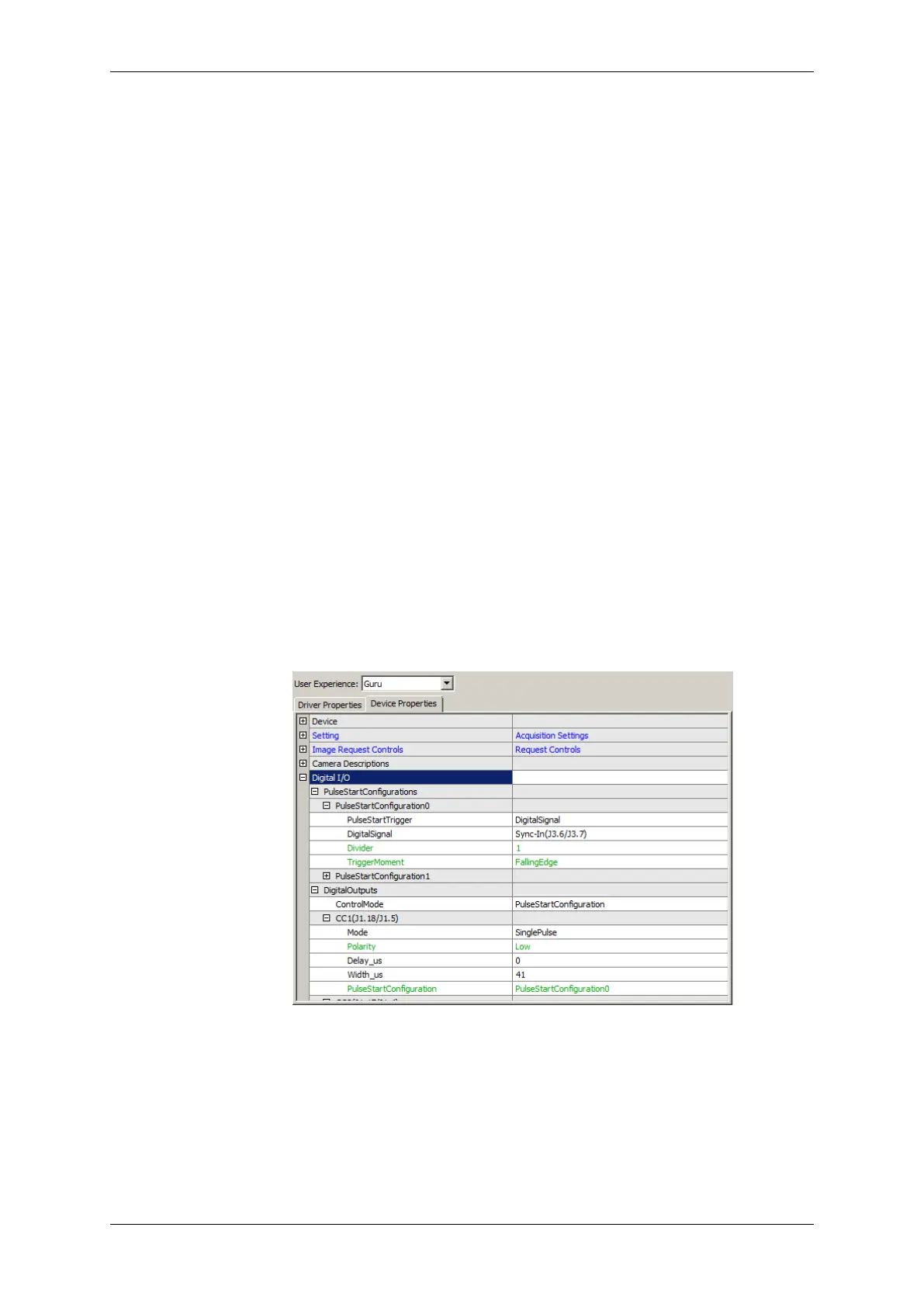
The following sample shows, how a SinglePulse with 41 us width at CC1 is defined, which
will start after a FallingEdge at the Sync-In input:
Figure 1: wxPropView - Pulse start sample
• Working with an rotary encoder (p. 124)
– parameters :
*
external signals from a rotary encoder, which starts the pulse sequence initially -> "Rotary←-
Decoder"
*
decode the signals of the rotary encoder.
MATRIX VISION GmbH