8.3 mvHYPERION-HD-SDI 43
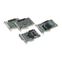
8.3.2.2 Pinning J5 (15-pol D-SUB/HD connector)
Figure 18: J5
Pin Signal Signal direction Level
1 Sync-Out 1 (Trilevel, 75R) OUT 1Vss (75R)
2 Sync-Out 2 (Trilevel, 75R) OUT 1Vss (75R)
3 Sync-Out 3 (Trilevel, 75R) OUT 1Vss (75R)
4 ID2 IN/OUT TTL (open collector)
5 Digital Ground RS-485 GND -
6 Ground Sync-Out 1 GND -
7 Ground Sync-Out 2 GND -
8 Ground Sync-Out 3 GND -
9 Camera Power Supply OUT +5VDC / >=10W (optional +12VDC)
10 Ground Sync GND -
11 ID0 IN/OUT TTL (open collector)
12 RS-485 TRX- IN/OUT RS485-
13 C/HSync-Out OUT TTL (push pull)
14 VSync-Out OUT TTL (push pull)
15 RS-485 TRX+ IN/OUT RS485+
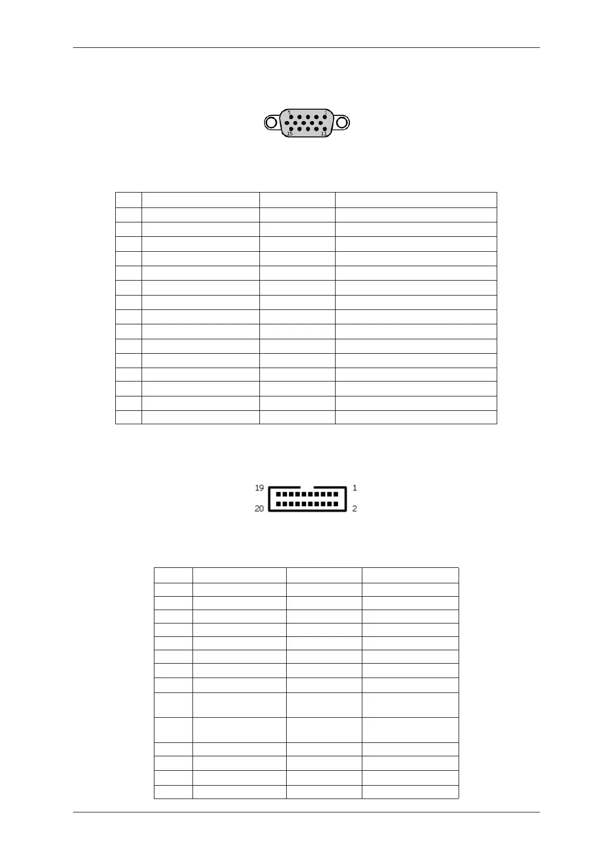
8.3.2.3 Pinning J6 (internal digital I/Os)
Figure 19: J6
Pin Signal Signal direction Level
1 NC - -
2 Ground GND -
3 SCL IN/OUT LVTTL
4 Ground GND -
5 SDA IN/OUT LVTTL
6 Ground GND -
7 +5V power supply OUT +5V DC
8 +3.3V power supply OUT +3.3V DC
12..9 GPIN3..0 IN LVTTL(3.3V) input.
not 5V tolerant!
16..13 GPOUT3..0 OUT LVTTL(3.3V) output.
not 5V tolerant!
17 Ground GND -
18 +12V power supply OUT +12V DC
19 +12V power supply OUT +12V DC
20 Ground GND -
MATRIX VISION GmbH