34 Chapter 2: Getting started with your Matrox 4Sight EV6 unit
Warning
The Matrox 4Sight EV6 auxiliary output signals are compatible with voltages up
to 24 V. However, by default, the auxiliary output signals offer low resistance.
When they are on (their circuit is closed), current flows directly through them.
Ensure that the circuit created between the power source, the output signal, the
connected device, and return path does not cause more than 100 mA to flow
through the signal.
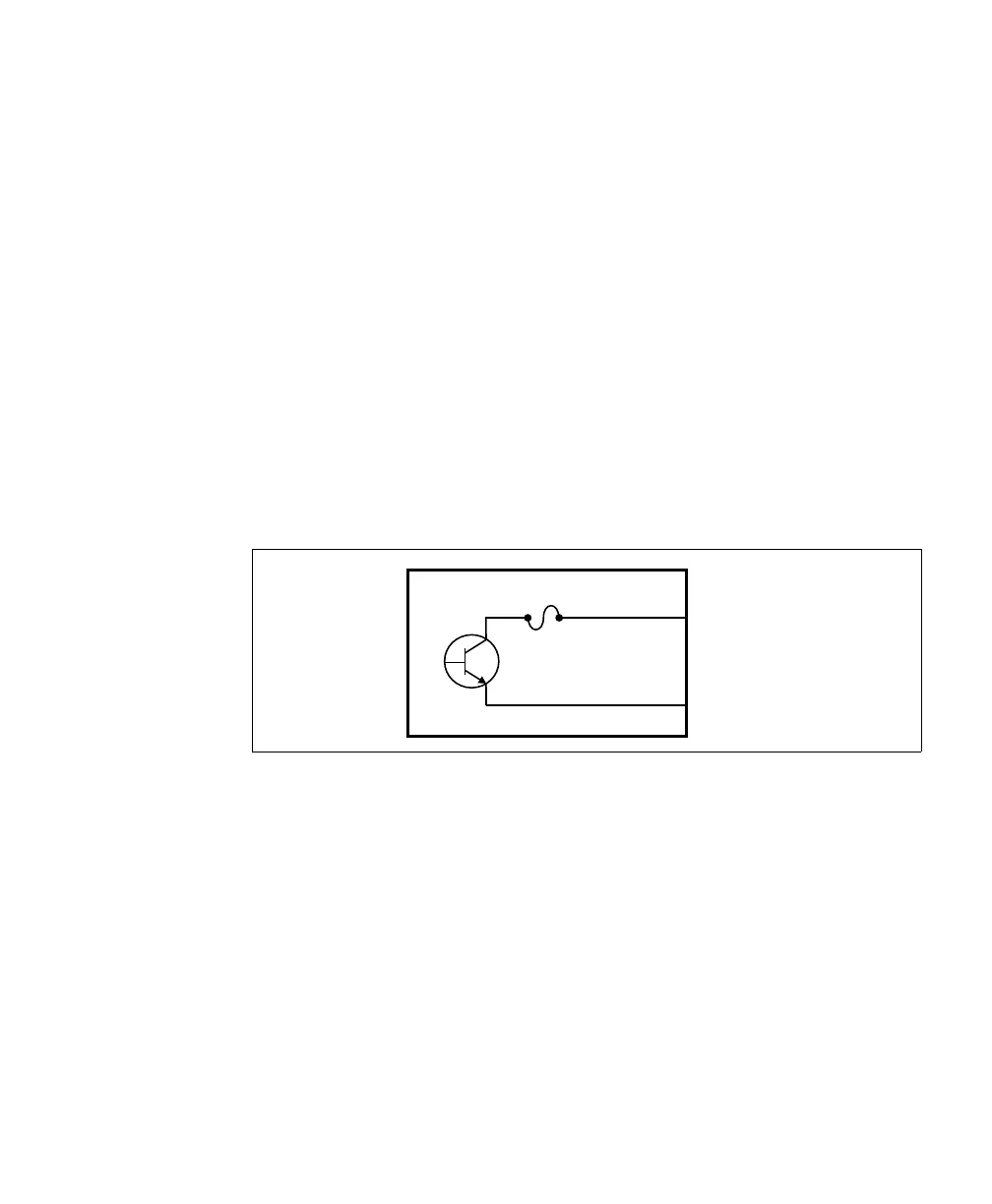
Fuse protection As a precaution, the auxiliary output signals are individually fuse-protected up to
100
mA. Matrox 4Sight EV6 uses resettable fuses. The fuses protect
Matrox
4Sight EV6 if you accidentally connect their corresponding auxiliary
output signal to a device that sources/sinks more current than Matrox
4Sight EV6
can safely transmit. If more than 100
mA of current goes through, the fuse will
eventually trip. After disconnecting your Matrox
4Sight EV6, the fuse will reset
only after it has sufficiently cooled.
The diagram below depicts Matrox 4Sight EV6’s on-board fuse.
About the
connections in the
following
subsections
The following subsections detail how to connect the most common third-party
devices to the Matrox
4Sight EV6 auxiliary output signals. Ground is only shown
in the following subsections for reference, in case you need to reference your return
path to ground.
Power, as depicted in the following diagrams, represents a nominal voltage of up
to 24
V (+/- 10%). For minimum and maximum voltage requirements, refer to
the electrical specification of the auxiliary output signals, in the
Matrox 4Sight
EV6 electrical specifications section, of Appendix B: Technical reference.
Equivalent circuit only
fuse
max.
100 mA
AUX_OUTn+
AUX_OUTn-