40 Chapter 2: Getting started with your Matrox 4Sight EV6 unit
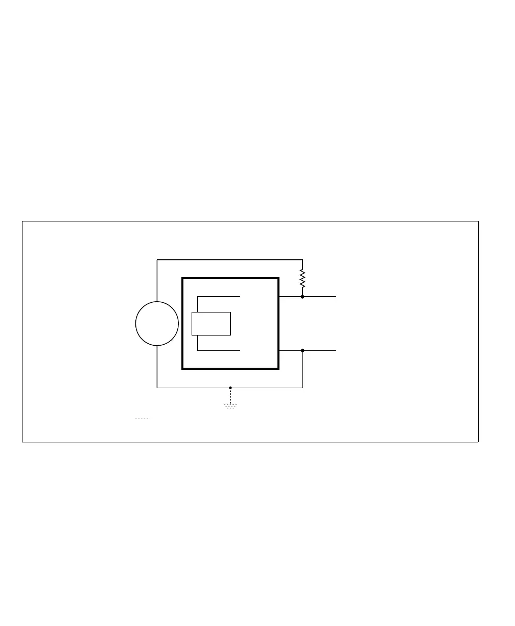
Pullup circuitry In some cases, you must add pullup circuitry to connect an output device to an
auxiliary input signal; specifically, you must attach an external pullup resistor
between the voltage source and the AUX_INn+ pin.
This is required when you connect the AUX_INn- pin to the electrical return path
and the third-party output device is sinking. In this case, select a resistor value that
will not over-current the output device and provides just enough current and
voltage to your Matrox
4Sight EV6 auxiliary input signals, according to the
Matrox 4Sight EV6 electrical specifications section in Appendix B: Technical
reference. Note that you should use a resistor with an appropriate power rating for
your circuit.
Equivalent circuit only
AUX INn-_
Connection required if using
external pullup circuitry
24V
Sensing
Circuit
AUX INn+_
+
-
Optional because the auxiliary input signals are electrically isolated.