23
2. COMPONENTS
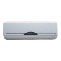
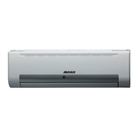
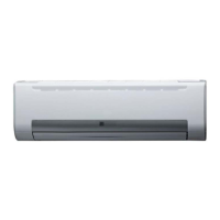
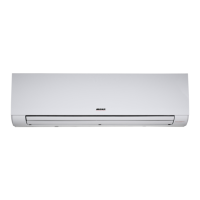
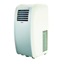
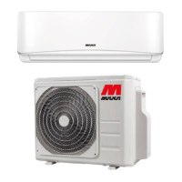
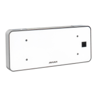
INDOOR UNIT
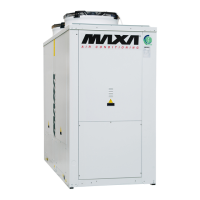
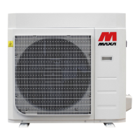
OUTDOOR UNIT
3. DISPLAY
(1) Aifr intake
(2) Front panel
(3) Control panel
(4) Air outlet
(5) Air flow louver
(6) Air filter
(7) Aifr intake
(8) Connecting pipe
(9) Drain
(10) Air outlet
(11) Air intake
(12) Remote controller
(1) LED signal receiver
(2) Operation indicator
This indicator flashes after power is on and illuminates when the unit is in operation.
(3) Heating indicator
This indicator illuminates during the operation in heating mode.
(4) Cooling indicator
This indicator illuminates during the operation in cooling mode.
(5) Setting temperature indicator
It displays the setting temperature during the operation of the air condizioner.
(6) Dehumidification indicator
It illuminates during the operation in dehumidification mode