OPERATING THE CONTROLLER5 - 2
D-MAXE with OI-TS www.maxcessintl.comMI 2-292 1 C
C Guide point display
Operating mode „Automatic“ and „Manual“: Guide point offset
of the active sensor
D Status line
Symbols see
Appendix B - Symbols, page 13-1
E Green marked button
Identifies the currently selected operation mode
FGray marked button:
This button has no function in the current system status.
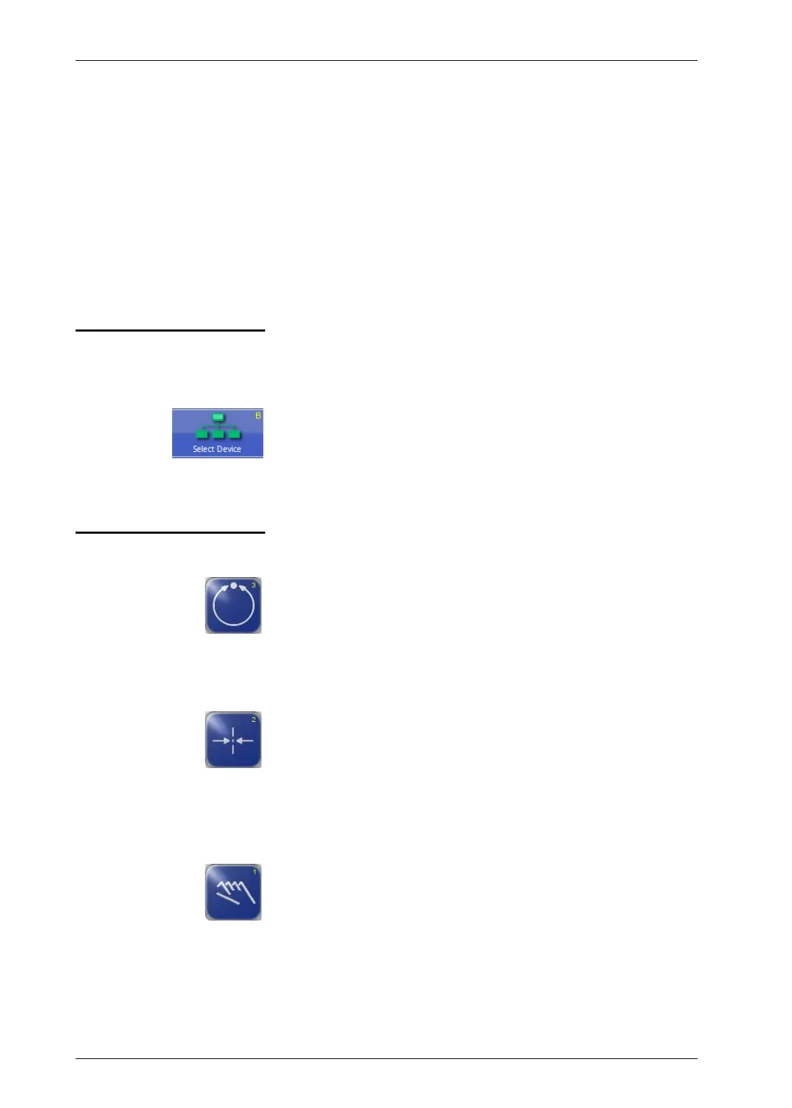
Select devices/actuators The OI-TS can be used to operate various devices present in the
network (D-MAX controllers and their actuators, any system
menus or gateways that are present).
∙ Touch the header and select menu
B Select Device
∙ Select the device you want to operate with the OI-TS
Select operating modes
Automatic
The web course is guided by an actuator based on sensor
information.
The bar graph represents the position of the material web in the
sensor's field of view.
Servo-center
The actuator is moved to the mechanical center position
depending on the servo-center transducer. Then the control
rollers are aligned parallel to the rollers of the customer system.
The bar graph indicates the current position of the actuator in
relation to the servo-center transducer.
Manual
There is no guiding of the web course. The settings of the
D-MAX system can be changed.
The bar graph represents the position of the material web in the
sensor's field of view.