INTRODUCTION 1 - 3
D-MAXE with OI-TSwww.maxcessintl.com MI 2-292 1 C
Einführung.fm
Operating principle The D-MAXE system consists of various modules that can be
combined depending on the specific application.
Modules D-MAXE Controllers
– integrated into a guiding system or for wall mounting
– D-MAXE 1 Controller:
for the drive of a control loop
– D-MAXE 2 Controller:
For the drive of two independent control loops
or
one control loop with automatic sensor positioning
– D-MAXE 3 Controller:
For the drive of three independent control loops or
combinations of control loops with automatic sensor
positioners
D-MAX Operator interfaces
– Operator interface OI-TS for desk installation or wall
mounting:
for operating of D-MAXE controllers or sensors
– PC-based virtual operator interface
Operating principle
Figure 1.4
shows an example of edge guiding (optionally center
guiding) with a D-MAXE system. The D-MAXE system consists of
a D-MAXE 1 Controller (1) and an operator interface OI-TS (2).
A sensor (3) senses the web edge of a material web and
determines the current position of the web. The D-MAXE 1
Controller receives this information and guides the material web
(5) by means of an actuator (4) so that it is always in the desired
target position.
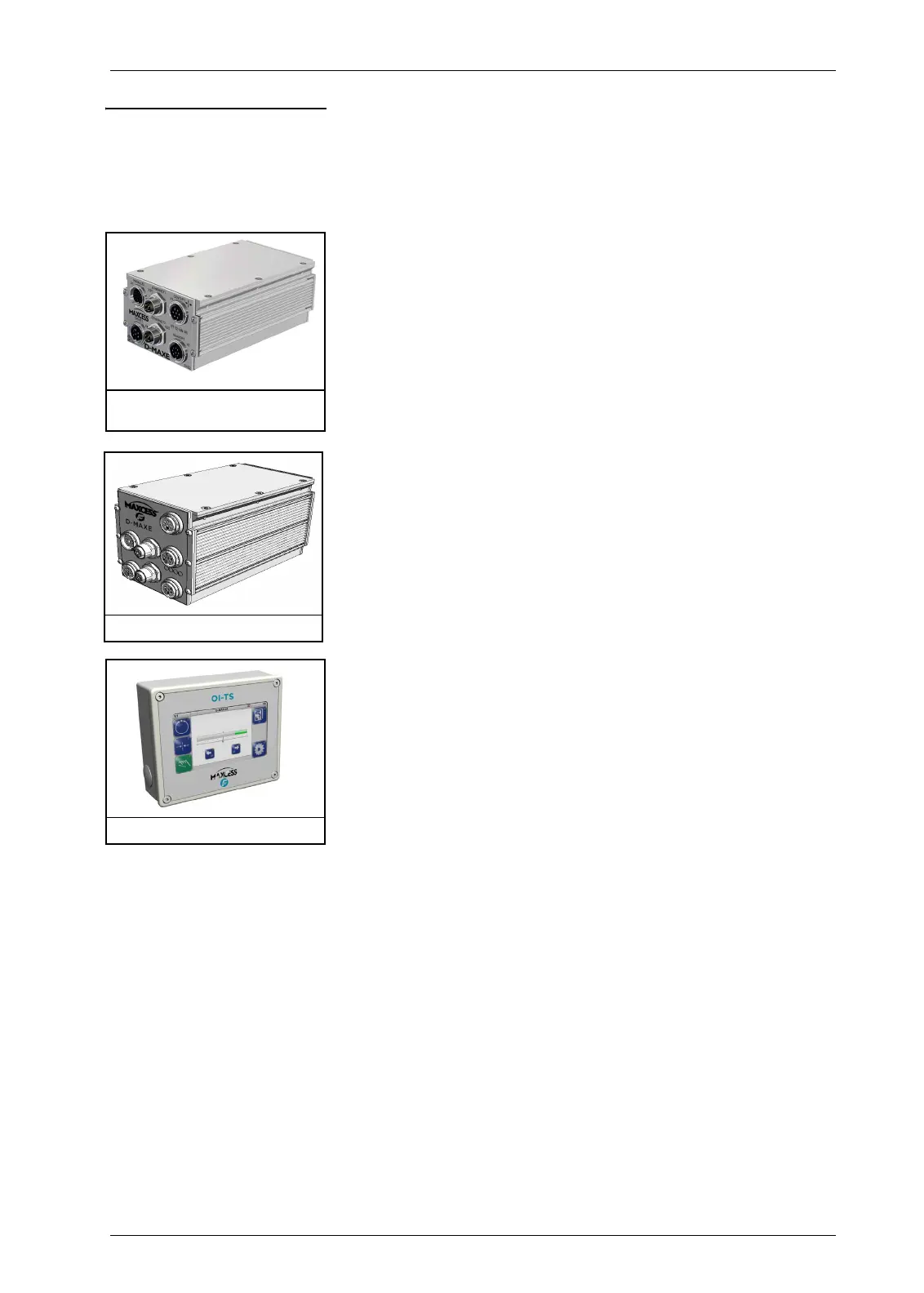
Figure 1.1: Controller, D-MAXE 1
and D-MAXE 2
Figure 1.2: Controller, D-MAXE 3
Figure 1.3: Operator interface