18
MAX Arm/Ultra Arm V1
2
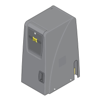
mount control box
115VAC
3A max
7A
FUSE
POWER
On
Off
WARNING: For continued protection
against fire, replace only with the
same type and rating of fuse.
AVERTISSEMENT: pour ne pas compromettre la
protection contre les risques d’incendie, utiliser un
fusible de mêmes type et caractéristiques nominales.
Select Input Voltage
115VAC or 230VAC
(AC)
POWER IN
115V
SAFETYCENTEREXIT
J3
J2
J4 J5
EXIT PWR
ALARM
POWER /
SOLAR IN
BATTERY
INPUT
OPENING CLOSING
MOTOR 2MOTOR 1
ERD
OBD PORT
BLACK BOX
PROGRAMMING
SOLAR MODE
MOTOR
OVER
LOAD
ERD
MOTOR
OVER
LOAD
MIN MAX
OFF
MAX
SENSE
MAX
SENSE
BATTERY
BACKUP MODE
ERD SENSITIVITY
MOTION CONTROL
OPEN
CLOSING GATE SPEED
MOTOR 2
LIMITS
MAG
LOCK
UL
ENTRAP
STOP CLOSE
CLOSE
TIMER
MAGLOCK
DELAY
JOG
BATTERY
TEST
BATTERY
INPUT
ERROR
BATTERY
IN USE
POWER
REPLACE
BATTERY
LEAVE
CLOSED
LEAVE
OPEN
OPEN
1 TIME
BATTERY VOLTAGE
EF1/2
RESET
ID
PLUG
MODULE
PORT
GATE OPEN
GND
OPEN ONLY NC
OPEN ONLY 10K
PHOTO CLS NC
OPEN / CLS NC
GND
12VDC OUT
GND
GND
GND
GND
GND
JOG CLOSE
JOG OPEN
TAMPER IN
TAMPER NO
GATE DISABLE
KEYPAD/CARD
GND
GND
MAX OPEN
FIRE DEPT
RADIO GND
RADIO SIGNAL
STRIKE
CLOSE
COM
COM
STOP
OPEN
CLS ONLY 10K
OPEN / CLS 10K
12VDC OUT
NO
COM
NC
COM
GATE CLOSED
LIMIT 1
GND
LIMIT 2
MOTOR 1
LIMITS
MOTOR 1
MOTOR 2
LIMIT 1
GND
LIMIT 2
LIMIT 1
LIMIT 2
LIMIT 1
LIMIT 2
ID PLUG
ERROR
24VDC OUTPUT
12VDC OUTPUT
GND
GND
GND
LOOP
LOOP PWR
LOOP
CENTER
SAFETY
OFF
SINGLE
OPEN
ON/OFF
BATTERY
CLOSE
DUAL
ON
ANTI-
TAILGATE
PUSH
OPEN
PULL
OPEN
GATE
OFF
1
2
3
4
5
6
7
8
9
10
OFF
1
2
3
4
5
6
MIN
MIN
MAX
MAX
ON
OFF 2.5 sec
1.5 sec
FAULTS
OPERATOR
DSP ARM CONTROLLER
OFF
EXIT LOOP
16
MIN
16
MIN
3
1
14 12
9
7
3
1
14 12
9
7
UL SENSOR 10K UL SENSOR N.C.
MODE A MODE B
PROGRAM
MOTOR 1
INPUTS
[
+
]
[
-
]
[
+
]
[
-
]
MOTOR 2
INPUTS
MAXIMUM CONTROLS
DSP ARM CONTROLLER
13.5”
5.75”
17”
1 1/2”
2 1/8”
Knock-Outs
3/4” Conduit
Knock-Outs
2 1/2”
2 1/2”
4 1/2” 4 1/2”
3”
2 1/2”
Front
Bottom
Side
JOG GATE
OPEN / CLOSE
RESET ALARM
Mount the control box as near as possible to the actuator arm. Avoid drilling holes in the side or top of the box.
Seal any holes made in box to keep out moisture.
Use the knock-outs to run desired 3/4” conduit.
Never run low voltage wires in the same conduit
as high voltage wire.
CAREFULLY remove the
delicate control board and
other components before
mounting box. Use the 4
mounting holes to install
box. See components
connections to help with
re-installation.
Couplings and conduit
not provided
Use flexible conduit to connect
to control box, not provided.
EXIT PWR
ALARM
POWER /
SOLAR IN
BATTERY
INPUT
OPENING CLOSING
MOTOR 2MOTOR 1
ERD
OBD PORT
BLACK BOX
PROGRAMMING
SOLAR MODE
MOTOR
OVER
LOAD
ERD
MOTOR
OVER
LOAD
MIN MAX
OFF
MAX
SENSE
MAX
SENSE
BATTERY
BACKUP MODE
ERD SENSITIVITY
MOTION CONTROL
OPEN
CLOSING GATE SPEED
MOTOR 2
LIMITS
MAG
LOCK
UL
ENTRAP
STOP CLOSE
CLOSE
TIMER
MAGLOCK
DELAY
JOG
BATTERY
TEST
BATTERY
INPUT
ERROR
BATTERY
IN USE
POWER
REPLACE
BATTERY
LEAVE
CLOSED
LEAVE
OPEN
OPEN
1 TIME
BATTERY VOLTAGE
EF1/2
RESET
ID
PLUG
MODULE
PORT
GATE OPEN
GND
OPEN ONLY NC
OPEN ONLY 10K
PHOTO CLS NC
OPEN / CLS NC
GND
12VDC OUT
GND
GND
GND
GND
GND
JOG CLOSE
JOG OPEN
TAMPER IN
TAMPER NO
GATE DISABLE
KEYPAD/CARD
GND
GND
MAX OPEN
FIRE DEPT
RADIO GND
RADIO SIGNAL
STRIKE
CLOSE
COM
COM
STOP
OPEN
CLS ONLY 10K
OPEN / CLS 10K
12VDC OUT
NO
COM
NC
COM
GATE CLOSED
LIMIT 1
GND
LIMIT 2
MOTOR 1
LIMITS
MOTOR 1
MOTOR 2
LIMIT 1
GND
LIMIT 2
LIMIT 1
LIMIT 2
LIMIT 1
LIMIT 2
ID PLUG
ERROR
24VDC OUTPUT
12VDC OUTPUT
GND
GND
GND
LOOP
LOOP PWR
LOOP
CENTER
SAFETY
OFF
SINGLE
OPEN
ON/OFF
BATTERY
CLOSE
DUAL
ON
ANTI-
TAILGATE
PUSH
OPEN
PULL
OPEN
GATE
OFF
1
2
3
4
5
6
7
8
9
10
OFF
1
2
3
4
5
6
MIN
MIN
MAX
MAX
ON
OFF 2.5 sec
1.5 sec
FAULTS
OPERATOR
DSP ARM CONTROLLER
OFF
EXIT LOOP
16
MIN
16
MIN
3
1
14 12
9
7
3
1
14 12
9
7
UL SENSOR 10K UL SENSOR N.C.
MODE A MODE B
PROGRAM
MOTOR 1
INPUTS
[
+
]
[
-
]
[
+
]
[
-
]
MOTOR 2
INPUTS
MAXIMUM CONTROLS
DSP ARM CONTROLLER
Components Connections
Battery Plug
Toroid Box Connector
Jog Gate
Open/Close
Jog Gate
Open/Close
See
page 35
Reset
Alarm
Reset Alarm
Button:
See
page 35
Alarm
Loop Rack
Operator
Cable
Loop
Ground
White-
Purple-
Blue-
Green-
Yellow-
Brown-
Black-
Exit Pwr
Exit Loop
Gnd
Center Loop
Loop Pwr
Safety Loop
Faults
Yellow-
Gray-
Black-
Jog Open
Jog Close
Gnd
Board
Ground
SAFETYCENTEREXIT
J3
J2
J4 J5
Red
Red
Make sure there is slack in the operator cable.
DO NOT over-bend the operator cable.
Doing this will cause the cable to eventually break.
DO NOT install near sprinklers or any area that
may expose the system to water.
Radio Receiver
Back
11”
Mounting
Hole
Mounting
Hole
Mounting
Hole
Mounting
Hole
6 1/8”
4 Mounting Holes
Mounting hardware
not provided
10”
1 1/4”
1 1/4”
1”
Please read all the “SAFETY
PAGES” in front of this manual
(pages 4-11) for installation
requirements and restrictions.
Overview of DSP circuit board
on page 54 for reference.
NOTE: Operator
cable should be in
flexible Conduit
(not provided).
Operator wire
should be in
flexible Conduit,
not provided.
Flex
Conduit
J-Box