25
11921 Slauson Ave. Santa Fe Springs, CA. 90670 (800) 227-4116 FAX (888) 771-7713
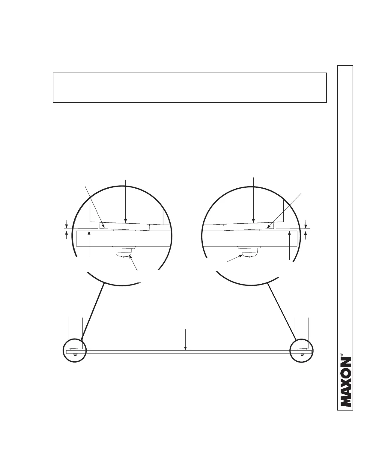
STEP 3 - POSITION LIFTGATE - Continued
METHOD 1 - PRE-INSTALL MOUNTING PLATES
AND EXTENSION PLATE ON VEHICLE - Continued
NOTE: Before welding mounting plates to vertical posts on vehicle body, check to
make sure LH and RH mounting plates are positioned within dimensions
shown in FIGS. 25-1A and 25-1B.
4. Place a straight edge across LH and RH
mounting plates (FIG. 25-1). Ensure that any
gap between the mounting plates and straight
edge (FIGS. 25-1A and 25-1B) are less than
1/16” maximum.
TOP VIEW MOUNTING PLATES
FIG. 25-1
LH
MOUNTING PLATE
FIG. 25-1A
MOUNTING
PLATE
MOUNTING
PLATE
RH
MOUNTING PLATE
FIG. 25-1B
TOP HANGER
TOP HANGER
1/16”
MAX.
1/16”
MAX.
VEHICLE BODY
VEHICLE BODY
STRAIGHT
EDGE
STRAIGHT
EDGE
STRAIGHT
EDGE
 Loading...