90
11921 Slauson Ave. Santa Fe Springs, CA. 90670 (800) 227-4116 FAX (888) 771-7713
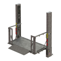
STEP 20 - ADJUST PLATFORM ASSEMBLY
1. Ensure aluminum platform is com-
pletely unfolded (FIG. 90-1). Use long
straight edge to determine if top sur-
face of platform is fl ush with top sur-
face of fl ipover as shown in FIG. 90-1.
2. If fl ipover requires adjustment, fold
platform enough to gain access
to adjustment bolt on each side of
platform (FIG. 90-2). Next, loosen
locking nut for each adjuster bolt
(FIG. 90-2). Then, alternately turn
each bolt clockwise to raise tip of
fl ipover or counter-clockwise to
lower tip of fl ipover. Repeat 1 to
check. When platform and fl ipover
are fl ush, torque both locking nuts
to 192 lb-ft.
ADJUSTER
BOLT FLAT
(SEE NOTE)
LOCKING
NUT
NORD-LOCK
WASHERS
ARROWS INDICATE WHERE TO CHECK
IF PLATFORM & FLIPOVER ARE FLUSH
FIG. 90-1
SIDE
PLATE
PLATFORM ADJUSTMENT BOLT
FIG. 90-2
NOTE: Recommend turning bolt in
60° increments so fl ats of the
adjuster bolt are parallel to
vertical surface of side plates.
 Loading...