39
11921 Slauson Ave. Santa Fe Springs, CA. 90670 (800) 227-4116 FAX (888) 771-7713
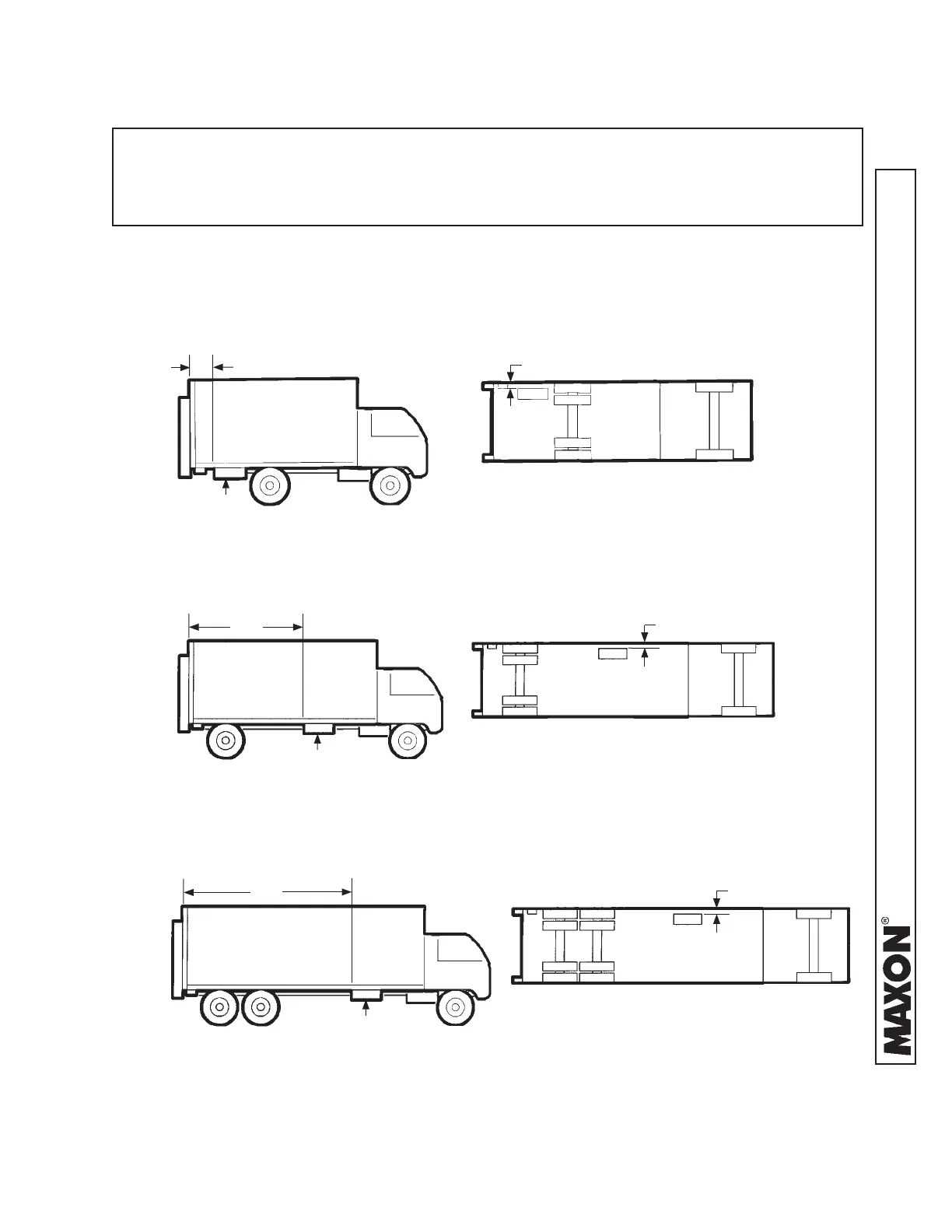
STEP 6 - POSITION PUMP BOX FRAME
Position pump box frame (or optional battery box) on the ground where it will be welded to
vehicle body in the next step. Make sure pump box (and battery box if supplied) are se-
curely bolted to the frame. Typical installations are shown in FIGS. 39-1, 39-2, 39-3, 40-1,
40-2, and 40-3.
TYPICAL 3 FT. INSTALLATION
FIG. 39-1
12”
12” - 36”
(Viewed from under truck.)
NOTE: Make sure pump box is closer to Liftgate than battery box (if installed) and pump
box cover opens toward curb-side of vehicle. Also, make sure hydraulic hoses are
installed without straining hoses. Distance from pump box to Liftgate is limited by
lengths of hydraulic hoses and wiring harness supplied with Liftgate.
PUMP BOX
10’
(Viewed from under truck.)
TYPICAL 10 FT. INSTALLATION
FIG. 39-2
PUMP BOX
12”
TYPICAL 15 FT. INSTALLATION
FIG. 39-3
12”
(Viewed from under truck.)
15’
PUMP BOX
 Loading...