19
11921 Slauson Ave. Santa Fe Springs, CA. 90670 (800) 227-4116 FAX (888) 771-7713
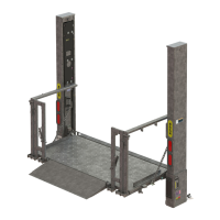
STEP 1 - PREPARE VEHICLE IF REQUIRED
1. Fabricate framework, as shown
in FIGS. 19-1A, -1B & -1C, to
support Liftgate on a fl atbed ve-
hicle. Then, go to the next page
for welding instructions.
NOTE: Materials for support framework are not provided with Liftgate.
RECTANGULAR TUBING, 1/8” WALL
ASTM-A36 GENERAL PURPOSE
STEEL, 2” x 4” x 70” LG.
(QTY. 2)
RECTANGULAR TUBING, 1/8” WALL
ASTM-A36 GENERAL PURPOSE
STEEL, 2” x 4” x 85” LG.
(QTY. 2)
RECTANGULAR TUBING,
1/8” WALL, ASTM-A36
GENERAL PURPOSE STEEL
2” x 4” x 88” LG. (96”WIDE BODY)
2” x 4” x 94” LG. (102”WIDE BODY)
(QTY. 1)
60”
36”
Approx.
RIGHT HAND (RH)
SUPPORT
LEFT HAND (LH)
SUPPORT
2”
VEHICLE BODY
SIDE RAIL
FLOOR PLATE,
1/4” THICK, ASTM-A36
GENERAL PURPOSE STEEL
4” x 10” LG.
(QTY. 2)
POSITIONING FLOOR PLATE
FIG. 19-1B
LOWER SUPPORT GUSSET,
1/4” THICK, ASTM-A36
GENERAL PURPOSE STEEL
8” x 8” LG. SIDES
(QTY. 2)
LOWER SUPPORT GUSSET,
1/4” THICK, ASTM-A36
GENERAL PURPOSE STEEL
8” x 16” LG. SIDES
(QTY. 2)
LIFTGATE SUPPORT
FRAMEWORK FOR FLATBED
FIG. 19-1A
POSITIONING GUSSETS
FIG. 19-1C
12”
(MAX. BELOW
BED HEIGHT)
32”
NOTE: LH and RH supports must be perpendicular to level ground. See VEHICLE
REQUIREMENTS, INSTALLED LIFTGATE.
NOTE: Perform the following step for fl atbed vehicle body only. If vehicle body is
not a fl atbed, skip this step.
Recommended practices for welding on steel parts are contained in the current
AWS (American Welding Society) D1.1 Structural Welding Code - Steel. Dam-
age to Liftgate and/or vehicle, and personal injury can result from welds that
are done incorrectly.
WARNING
!
 Loading...