29
11921 Slauson Ave. Santa Fe Springs, CA. 90670 (800) 227-4116 FAX (888) 771-7713
STEP 3 - POSITION LIFTGATE - Continued
ALTERNATE
2” LG. X 3
PLACES
INBOARD & 2”
LG. X 3 PLACES
OUTBOARD OF
LH & RH
COLUMNS OR
MOUNTING
PLATES
WELDING LIFTGATE TO
VEHICLE
FIG. 29-1
1/4”
1/4”
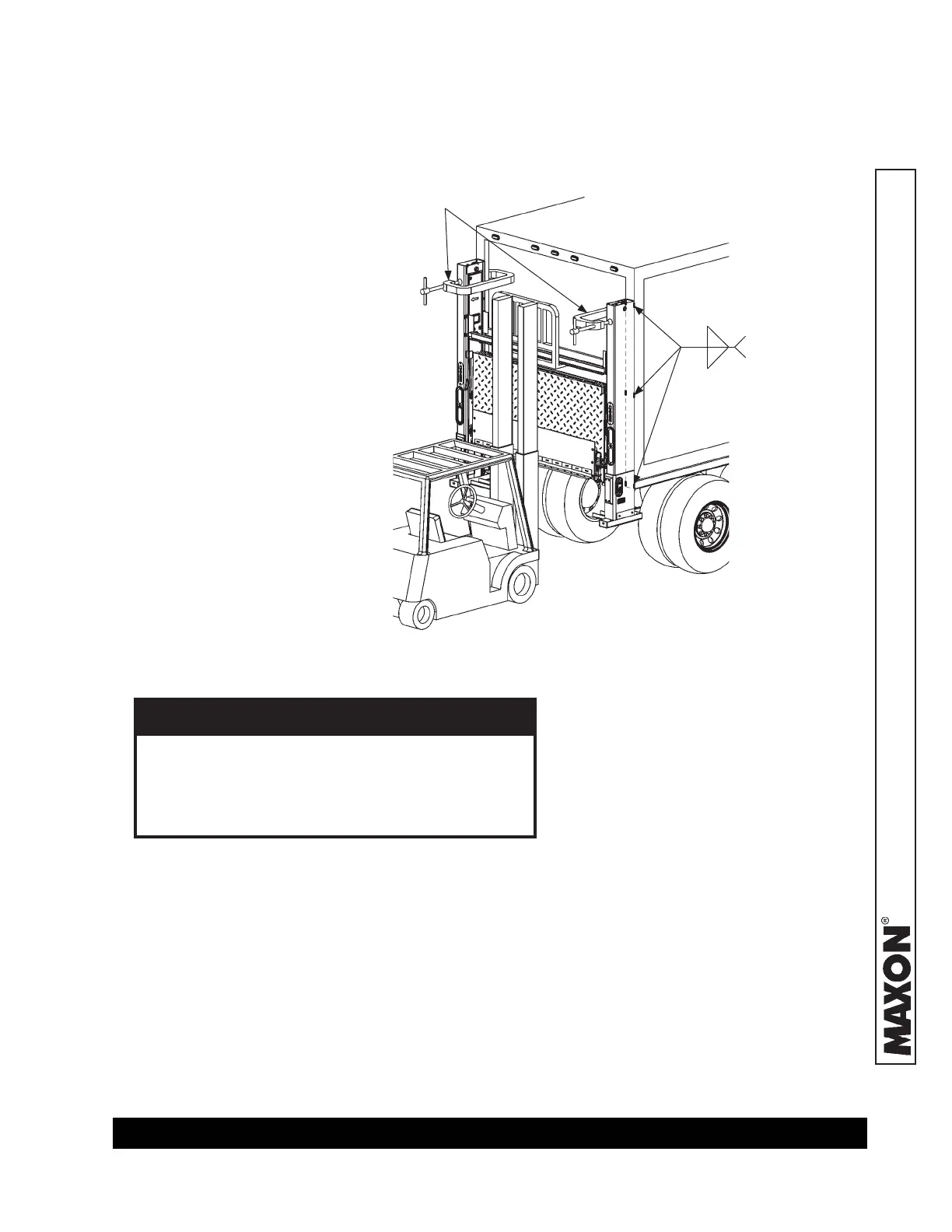
3. Use overhead hoist or fork
lift to center Liftgate
against the vehicle (FIG.
29-1). Let angle stock,
welded to extension plate,
rest on the top surface of
the vehicle bed.
4. Clamp top of each column
to vehicle body to prevent
gap (FIG. 29-1).
5. Weld the RH and LH columns
to vehicle body (FIG. 29-1).
TYPICAL
CLAMPS
6. Remove clamp from each of
the columns. Then, move fork-
lift away from work area.
GO TO STEP 5: REMOVE LOWER SUPPORT FIXTURES
To prevent damage to Liftgate:
• Connect welder ground to vehicle body.
• Protect hydraulic hoses and electrical
cables with fl ame-resistant cover.
CAUTION
METHOD 2 - WELD BOLT-ON LIFTGATE TO BODY - Continued
7. Check to make sure RH and LH columns
are square and perpendicular to the ex-
tension plate (FIG. 28-1).
 Loading...