52
11921 Slauson Ave. Santa Fe Springs, CA. 90670 (800) 227-4116 FAX (888) 771-7713
RUN HYDRAULIC LINES
STEP 8 - RUN HYDRAULIC LINES & ELECTRIC CABLES
- Continued
POWER DOWN PUMP BOX INSTALLATION: REQUIRED HOSES
3 FT. 10 FT. 15 FT.
1 HP 1/4” X 34” LG. HP 1/4” X 166” LG. HP 1/4” X 226” LG.
2 HP 1/4” X 64” LG. HP 1/4” X 188” LG. HP 1/4” X 248” LG.
3 HP 3/8” X 72” LG. HP 3/8” X 196” LG. HP 3/8” X 256” LG.
4 HP 3/8” X 150” LG. HP 3/8” X 274” LG. HP 3/8” X 334” LG.
TABLE 52-1
POWER DOWN PUMP BOX INSTALLATION: REQUIRED HOSES
20 FT. 28 FT.
1 HP 1/4” X 286” LG. HP 1/4” X 382” LG.
2 HP 1/4” X 308” LG. HP 1/4” X 404” LG.
3 HP 3/8” X 316” LG. HP 3/8” X 412” LG.
4 HP 3/8” X 394” LG. HP 3/8” X 490” LG.
TABLE 52-2
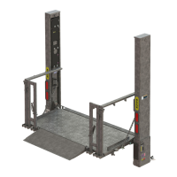
NOTE: Each pump extension kit contains 2 hoses of the same length (item 1).
One hose is for the Platform Fold Line and the second hose is for the
Platform Unfold Line. One hose has a yellow band on each connector
to help connect the 2 hoses to the correct fi ttings. For example, connect
hose with yellow bands to the Fold Line on the RH column and the Fold
Line on the back of the pump box.
NOTE: See TABLES 50-1, 50-2 & 50-3
for hydraulic fi ttings torque values.
 Loading...