64
11921 Slauson Ave. Santa Fe Springs, CA. 90670 (800) 227-4116 FAX (888) 771-7713
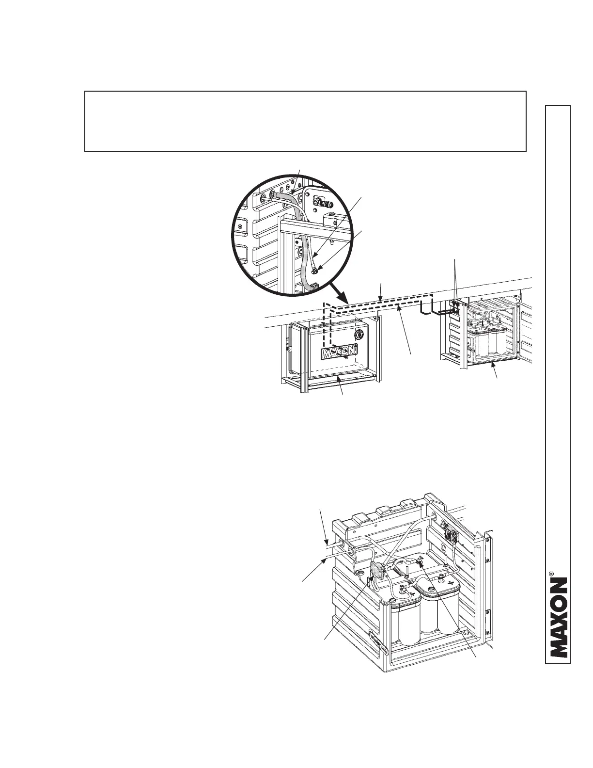
ELECTRICAL CONNECTIONS IN BATTERY BOX
FIG. 64-2
NOTE: The following instructions are only required if Liftgate is equipped with
optional battery box, and the pump box and battery box are mounted in
separate single frames. In the dual frame shown below, the power cable is
connected between pump box and battery box at the factory.
5. Uncoil the red (+) cable
from back of the pump
box (FIG. 64-1). Next, run
cable along vehicle frame,
through grommet on bat-
tery box, and to the 200
amp circuit breaker inside
battery box (FIG. 64-2).
STEP 11 - CONNECT BATTERIES TO LIFTGATE - Cont’d
PUMP BOX & BATTERY BOX IN SINGLE FRAMES
FIG. 64-1
PUMP BOX
BATTERY BOX
RED (+) CABLE
GROMMETS
RED (+)
CABLE
GROUND
STUD (REF)
BLACK (-)
CABLE
BLACK (-)
CABLE
RED (+) CABLE
TO PUMP BOX
NEGATIVE (-)
BATTERY TERMINAL
BLACK (-) CABLE
TO PUMP BOX
200 AMP CIRCUIT
BREAKER
6. Uncoil the black (-) cable
from back of the pump box
(FIG. 64-1). Next, run cable
along vehicle frame, through
grommet on battery box, and
to the negative (-) battery
terminal inside battery box
(FIG. 64-2).
 Loading...