Setup
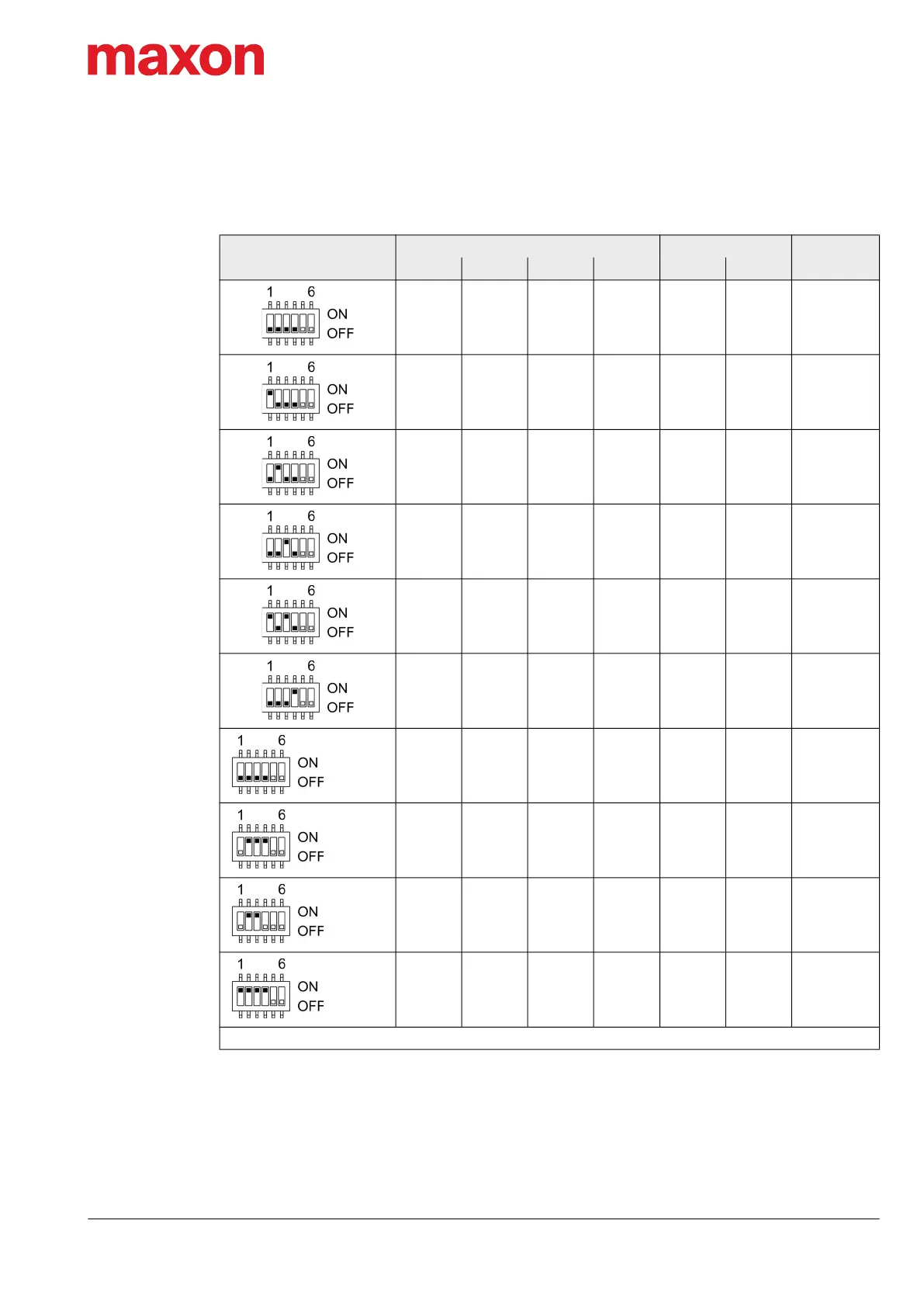
DIP Switch Configuration (SW1)
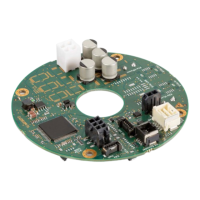
EPOS4 Disk 60/12 Hardware Reference
CCMC | 2022-05 | rel10685
3-57
The set ID can be observed by adding the valence of all activated switches. Use the following table as a
(non-concluding) guide:
Table 3-75 DIP switch SW1 – Examples
Setting
Switch Solder pad
ID
1 2 3 4 JP301 JP302
0 0 0 0 0 0 –
1 0 0 0 0 0 1
0 1 0 0 0 0 2
0 0 1 0 0 0 4
1 0 1 0 0 0 5
0 0 0 1 0 0 8
0 0 0 0 1 0 16
0 1 1 1 0 1 30
0 1 1 0 1 1 54
1 1 1 1 1 1 63
0 = Switch “OFF” / solder pad “open” 1 = Switch “ON” / solder pad “shorted”
JP301
closed
JP302
closed
JP301
JP302
closed
JP301
JP302
closed
 Loading...