Setup
Connections
EPOS4 Disk 60/12 Hardware Reference
3-44 CCMC | 2022-05 | rel10685
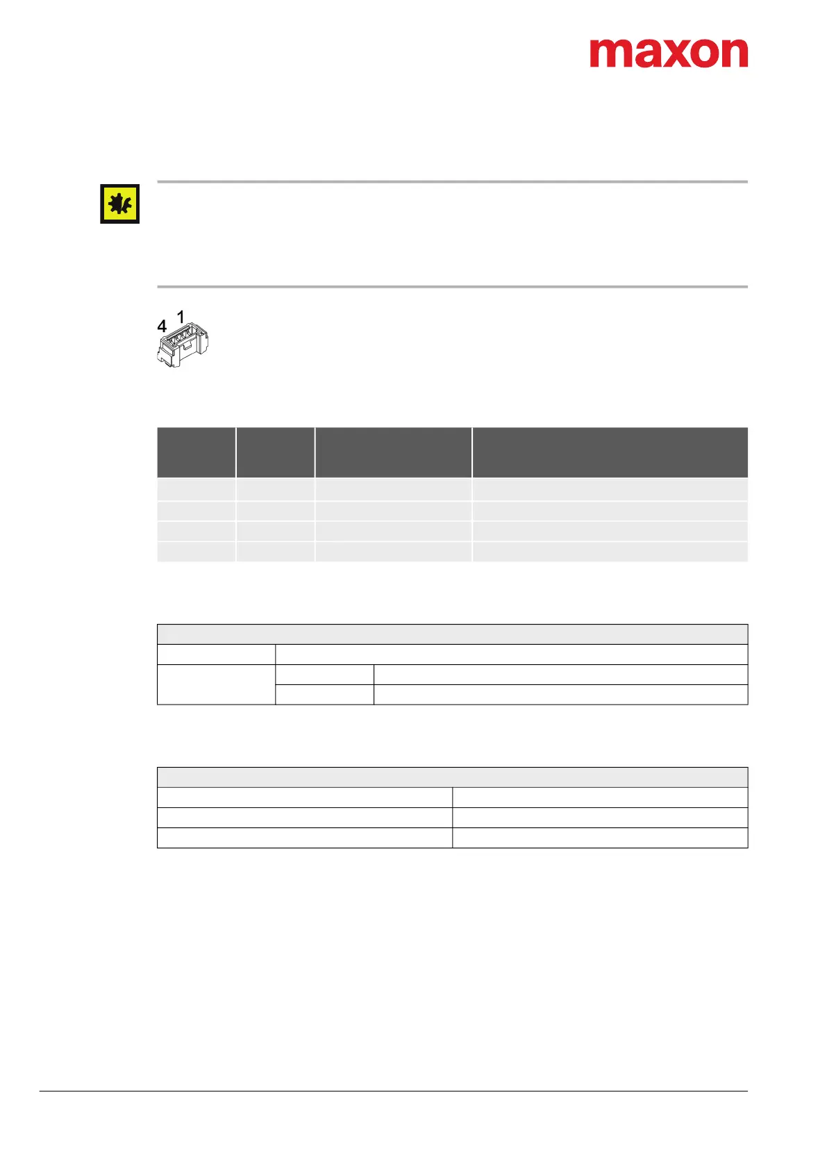
3.3.10 USB (X13; X13a)
Hot plugging the USB interface may cause hardware damage
If the USB interface is being hot-plugged (connecting while the power supply is on), the possibly high poten-
tial differences of the two power supplies of controller and PC/Notebook can lead to damaged hardware.
• Avoid potential differences between the power supply of controller and PC/Notebook or, if possible, bal-
ance them.
• Insert the USB connector first, then switch on the power supply of the controller.
Figure 3-34 USB connector X13 or X13a
Table 3-47 USB connector X13 or X13a – Pin assignment
Table 3-48 USB connector X13 or X13a – Specifications
Table 3-49 USB interface specification
X13
X13a
Pin
PC’s USB
Terminal
Pin
Signal Description
1 1
V
Bus
USB bus supply voltage input +5 VDC
2 2 USB_D− USB Data− (twisted pair with Data+)
3 3 USB_D+ USB Data+ (twisted pair with Data−)
4 4 GND USB ground
Connector X13; X13a
Suitable cable USB Type A-Micro-Lock Cable on page 3-52
Suitable plug
Housing Molex Micro-Lock (05055650401)
Contact Molex Micro-Lock (05054311000) AWG26…30
USB
USB Standard USB 2.0 / USB 3.0 (full speed)
Max. bus supply voltage +5.25 VDC
Max. DC data input voltage −0.5…+3.8 VDC
X13
X13a