Setup
Connections
EPOS4 Disk 60/12 Hardware Reference
3-32 CCMC | 2022-05 | rel10685
3.3.5 Encoder/Sensor (X5/X6)
Danger of multiple signal allocation
If you are using this combined encoder/sensor combo connector X5/X6, do not at the same time connect
the connectors X5 and X6!
The connector can provide connectivity for two different purposes. The respective pin assignment is
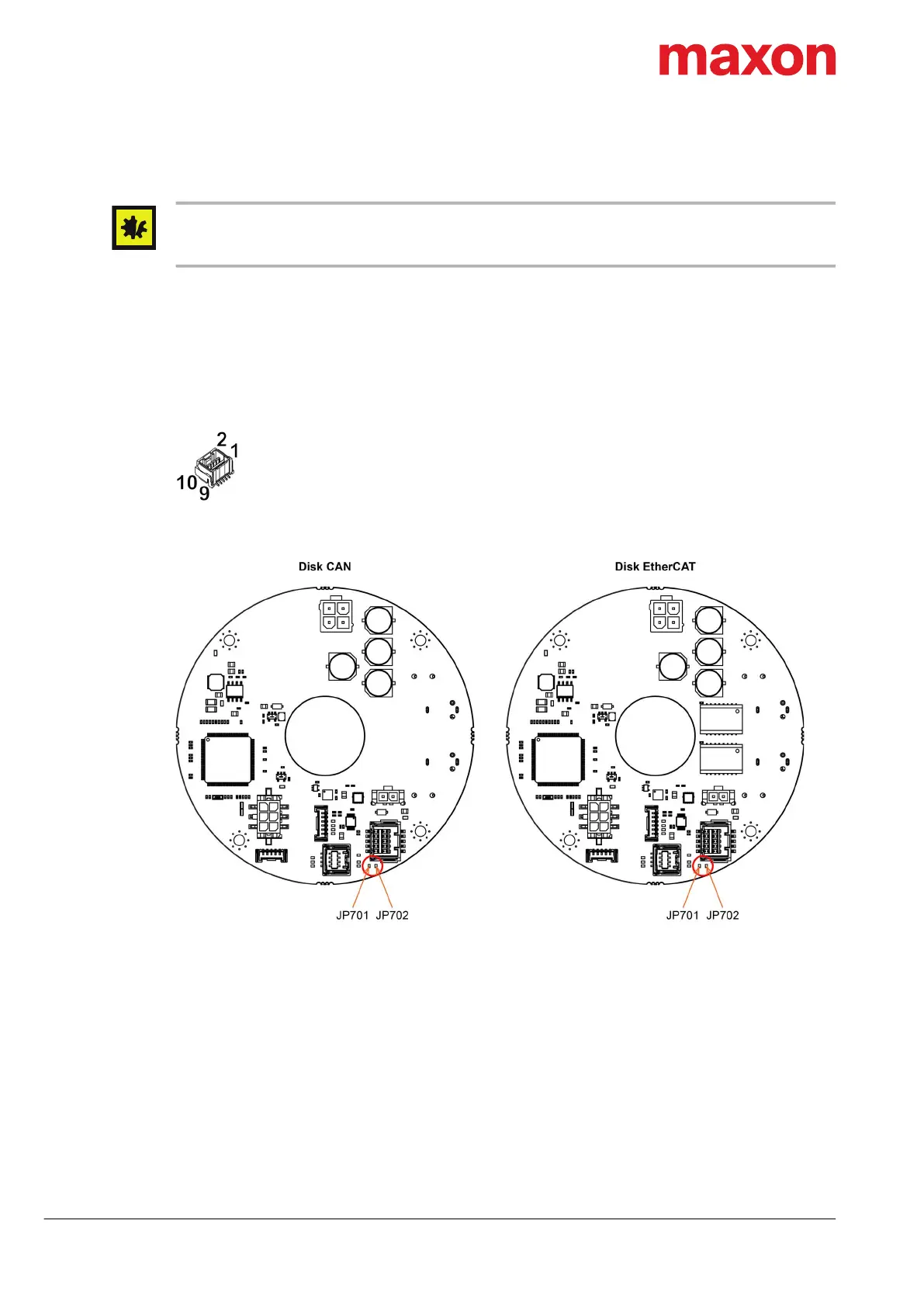
selected by either leaving open or shorting the solder pads JP701 and JP702 (for their location see
Table 3-19).
• Variant A: the solder pads JP701 and JP702 are left open (default factory setting), thus providing
connectivity for both a two-channel encoder (A, B) and a SSI encoder (Clock, Data)
• Variant B: the solder pads JP701 and JP702 are shorted, thus providing connectivity for a 3 three-
channel encoder (A, B, I)
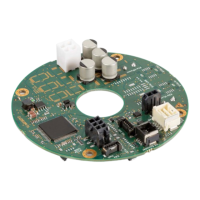
Figure 3-18 Encoder/Sensor combo connector X5/X6
Figure 3-19 Solder pads JP701, JP702 – Location
Continued on next page.
X5/X6