Setup
Connections
EPOS4 Disk 60/12 Hardware Reference
3-34 CCMC | 2022-05 | rel10685
3.3.6 Encoder (X5)
Danger of multiple signal allocation
If you are using this encoder connector X5, do not at the same time connect the combined encoder/
sensor combo connector X5/X6!
Best practice
• Differential signals offer good resistance against electrical interference. Therefore, we recommend
using a differential scheme. Nevertheless, the controller supports both schemes – differential and sin-
gle-ended (unsymmetrical).
• For best performance, we strongly recommend to use encoders with a line driver. Otherwise, limita-
tions may apply due to slow switching edges.
• Even though 2-channel will do, we strongly recommend to use only 3-channel versions.
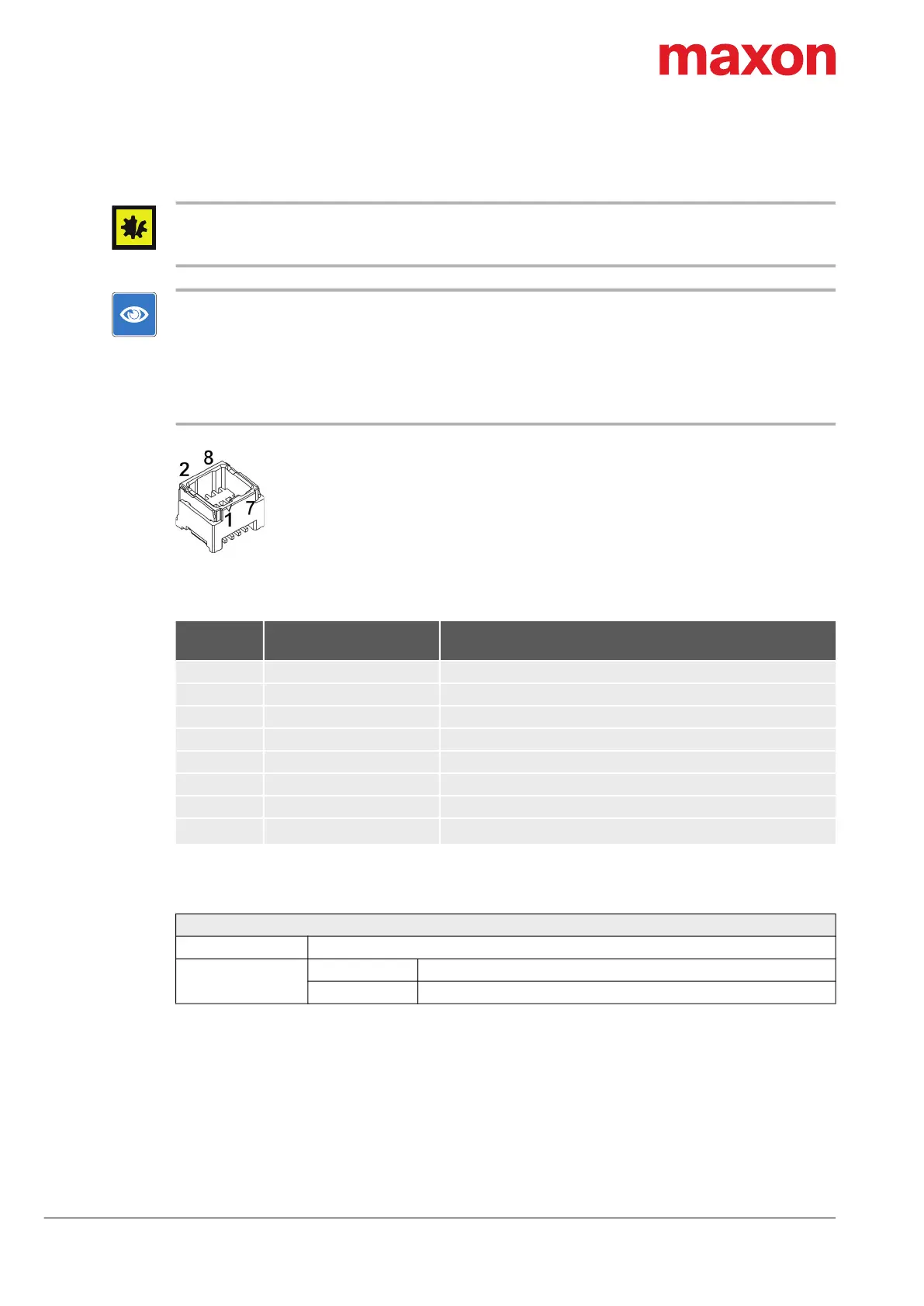
Figure 3-20 Encoder connector X5
Table 3-30 Encoder connector X5 – Pin assignment
Table 3-31 Encoder connector X5 – Specifications
Continued on next page.
X5
Pin
Signal Description
1 Channel A Channel A
2 Channel A\ Channel A complement
3 Channel B Channel B
4 Channel B\ Channel B complement
5 Channel I Channel I
6 Channel I\ Channel I complement
7 GND Ground
8
V
Sensor
Sensor supply voltage (+5 VDC; I
L
100 mA)
Connector X5
Suitable cable Encoder Cable on page 3-51
Suitable plug
Housing Molex Micro-Lock (05054320801)
Contact Molex Micro-Lock (05054311000) AWG26…30
X5