Wiring
Excerpts
EPOS4 Disk 60/12 Hardware Reference
CCMC | 2022-06 | rel10685
4-71
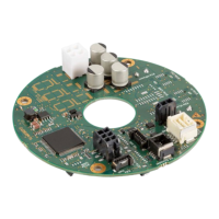
4.3.7 Digital Incremental Encoder (Sensor 1) on X5/X6
Figure 4-51 Digital incremental encoder (Sensor 1) on X5/X6
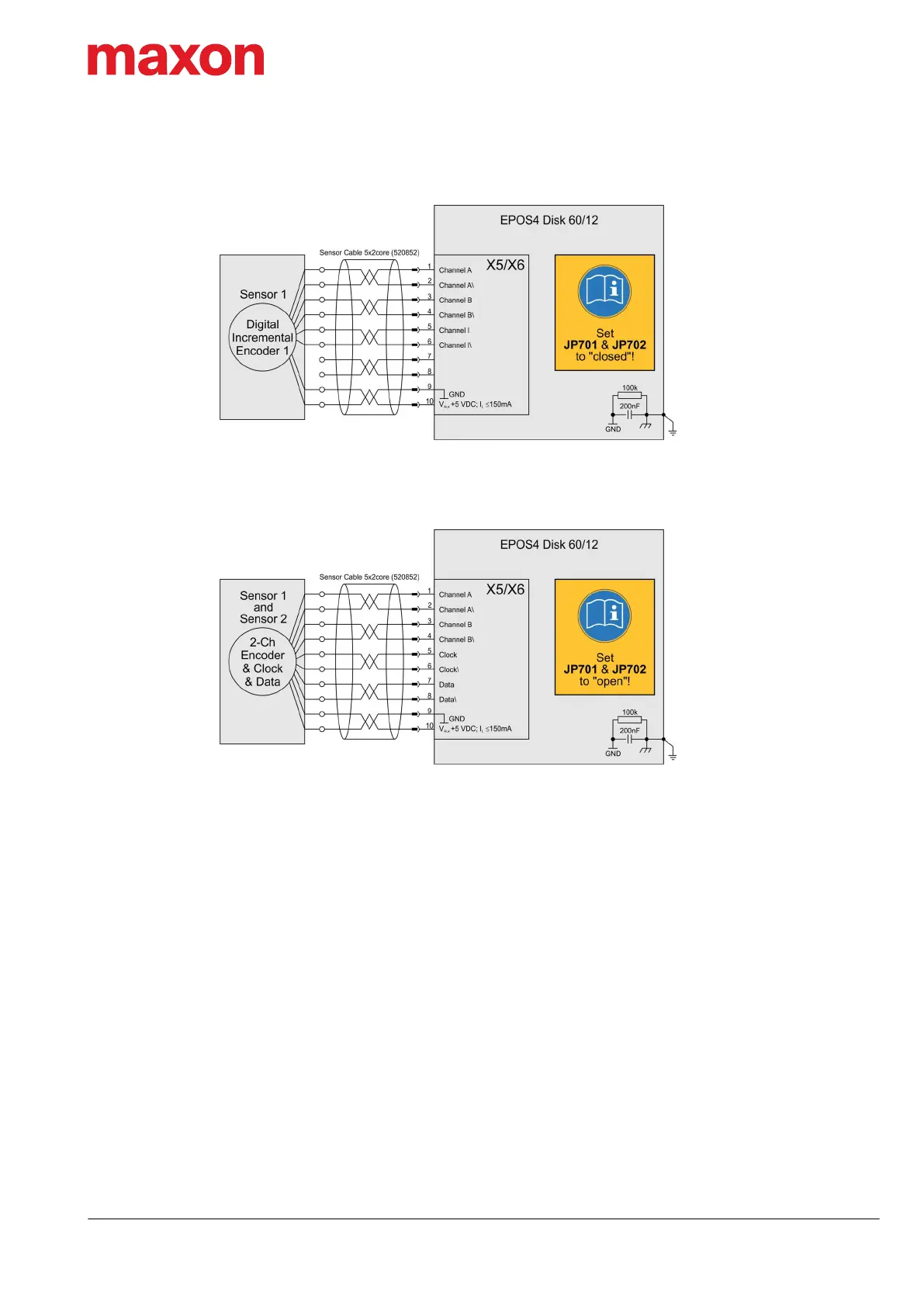
4.3.8 Digital Incremental Encoder (Sensor 1) and SSI Encoder (Sensor 2) on X5/X6
Figure 4-52 Digital incremental encoder (Sensor 1) and SSI encoder (Sensor 2) on X5/X6
The combo connector X5/X6 can
be configured using the solder
pads JP701 and JP702 (for
details see Figure 3-19 on
page 3-32).
For this setup, short-circuit
both solder pads JP701 and
JP702.
The combo connector X5/X6 can
be configured using the solder
pads JP701 and JP702 (for
details see Figure 3-19 on
page 3-32).
For this setup, leave open both
solder pads JP701 and JP702
(default factory setting).