MECHANICAL
01–10–21
01–10
End Of Sie
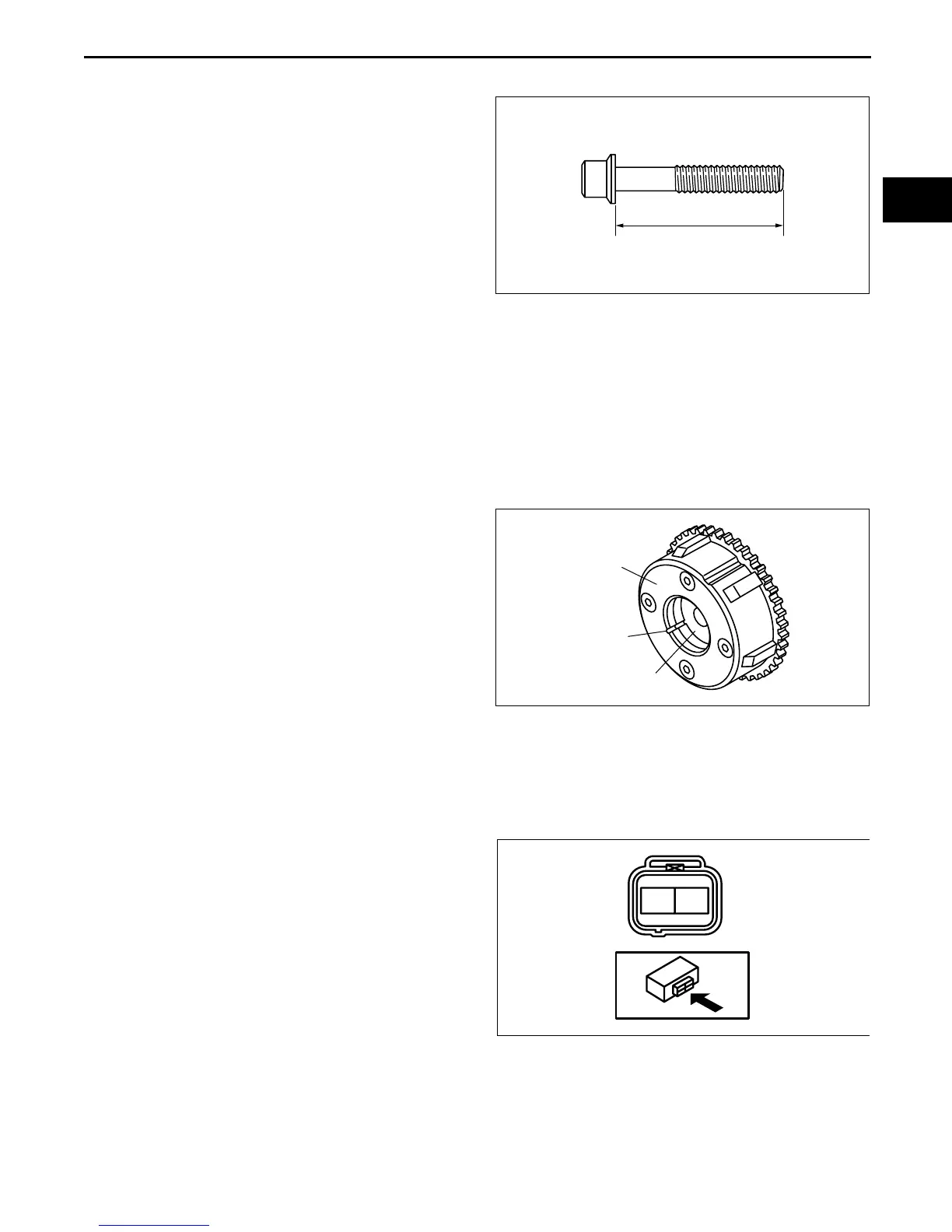
BOLT INSPECTION
E5U011010135E01
1. Measure the length of each bolt.
• If it exceeds the specification, replace the bolt.
Bolt length (mm {in})
Cylinder head bolt (With washer)
Standard: 149.2—149.8 {5.87—5.90}
Maximum: 150.5 {5.91}
Cylinder head bolt (Without washer)
Standard: 145.2—145.8 {5.72—5.74}
Maximum: 146.5 {5.77}
Connecting rod bolt
Standard: 44.7—45.3 {1.75—1.78}
Maximum: 46.0 {1.81}
Main bearing cap bolt (Plastic region
tightening bolt only)
Standard: 110.0—110.6 {4.33—4.35}
Maximum: 111.3 {4.38}
End Of Sie
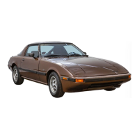
VARIABLE VALVE TIMING ACTUATOR INSPECTION [WITH VARIABLE VALVE TIMING MECHANISM]
E5U011012490E01
Caution
• Variable valve timing actuator cannot be disassembled because it is a precision unit.
1. Confirm that the groove of the rotor and notch of
the cover at the variable valve timing actuator are
aligned and fixed.
• If the notch and the bump are not aligned,
rotate the rotor toward the valve timing retard
position by hand until they are in place.
• If the rotor and cover are not fixed even
though their notch and groove are aligned,
replace the variable valve timing actuator.
End Of Sie
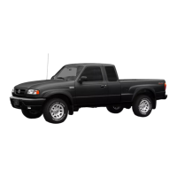
OIL CONTROL VALVE (OCV) INSPECTION [WITH VARIABLE VALVE TIMING MECHANISM]
E5U011014420E01
Coil Resistance Inspection
1. Disconnect the negative battery cable.
2. Disconnect the oil control valve (OCV) connector.
3. Measure the resistance between terminals A and B using an ohmmeter.
• If not as specified, replace the oil control valve (OCV).
Specification
6.9—7.9 ohms [20 °C {68 °F}]
4. Connect the oil control valve (OCV) connector.
L
B3E0110E088
COVER
NOTCH
ROTOR
B3E0110E089
AB
B3E0110W151