MECHANICAL
01–10–27
01–10
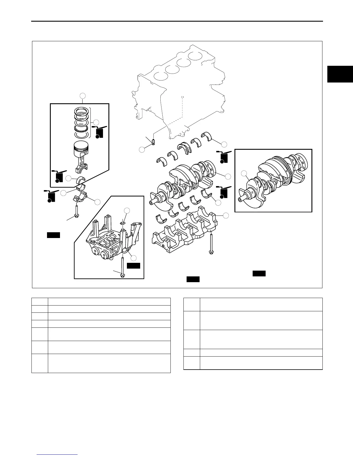
CYLINDER BLOCK (I) ASSEMBLY
E5U011002000E08
1. Assemble in the order indicated in the table.
.
OIL
OIL
OIL
OIL
OIL
4
3
3
2
1
SST
5
7
8
9
6
12
11
10
L3
L3
N·m {kgf·m, ft·lbf}
26—32 {2.7—3.2,
19.2—23.6}+80
°—100°
25+44—46
{2.6+4.5—4.7,
18.4+32.5—33.9}
2.9—4.9 N·m
{30—40 kgf·cm,
25.67—43.4 in·lbf}
ELASTIC REGION TIGHTENING BOLT
(BOLT STEM LENGTH 104 mm)
3—7 N·m {30.6—71.3 kgf·cm,26.6—61.9 in·lbf}
+23—27 {2.4—2.7, 17—19.9}
+38—42 {3.9—4.2, 28.1—30.9}
Loosen all the bolts
+3—7 N·m {30.6—71.3 kgf·cm,26.6—61.9 in·lbf}
+18—22 {1.9—2.2, 13.3—16.2}
+87.5
°—92.5°
PLASTIC REGION TIGHTENING
BOLT
(BOLT STEM LENGTH 110 mm)
44—46 {4.5—4.6, 32.5—33.9}
+175
°—185°
SST
SST
SST
E5U110ZE7S03
1 Oil jet valve
2 Upper main bearing, thrust bearing
3Crankshaft
4 Lower main bearing, thrust bearing
5 Main bearing cap
(See 01–10–28 Main Bearing Cap Assembly Note)
6
Piston ring
(See 01–10–28 Piston Ring Assembly Note)
7 Upper connecting rod bearing
(See 01–10–29 Connecting Rod Bearing Assembly
Note)
8 Connecting rod, piston assembly
(See 01–10–28 Piston Assembly Note)
9 Lower connecting rod bearing
(See 01–10–29 Connecting Rod Bearing Assembly
Note)
10 Connecting rod cap
(See 01–10–29 Connecting Rod Cap Assembly
Note)
11 Adjustment shim
12 Balancer unit
(See 01–10–29 Balancer Unit Assembly Note)