B20
VALVE MECHANISM
End Of Sie
CAMSHAFT
A6E221112420T01
Structure
• The cast iron 5 axis-hole, which has great rigidity, has been adopted for the camshaft to insure higher reliability.
• The endplay of the camshaft is regulated at the rear of the No. 1 journal.
• The lubricating oil is supplied through the oil supply hole at each journal. Additionally the cam nose part has
been chilled to improve the abrasion resistance and to make the cam hill part lightweight by shortening the
width.
• The positioning pin or key slot, which was used when installing the camshaft sprocket to the edge of the
camshaft, has been decommissioned. And the lubrication process has been adopted for the camshaft sprocket
tightening bolt to prevent instability in the axis during tightening.
• There is an oil line, by which the oil is supplied to the variable valve timing actuator, located at the L3 engine
models intake port side camshaft (front of camshaft).
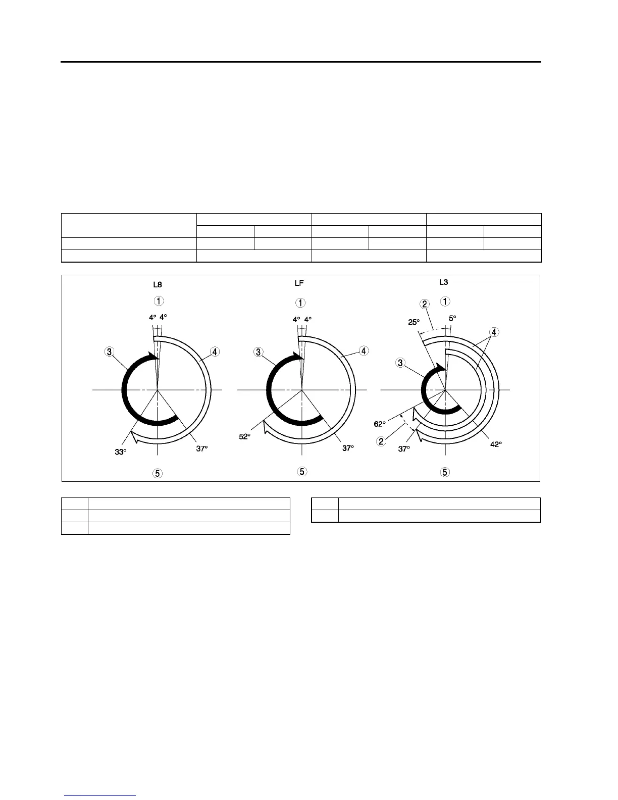
Camshaft Specification.
.
• The detection unit or the camshaft position (CMP) sensor, which is integrated with the camshaft, is at the intake
port side camshaft for L8 engine models and LF engine models.
• The detection unit (trigger plate) for the camshaft position (CMP) sensor is at the intake port side camshaft for
L3 (with variable valve timing mechanism) engine models.
• The groove for securing the No.1 TDC for the camshaft, is provided at the rear of the intake and exhaust
camshaft.
ITEM
L8 LF L3
IN EX IN EX IN EX
LIFT (mm{in}) 7.5 {0.29} 7.7 {0.30} 8.8 {0.34} 7.7 {0.30} 9.1 {0.35} 7.8 {0.31}
Overlap (°)8 8 30
AME2211N004
1TDC
2 Variable domain
3EX
4IN
5BDC


 To Next Page