Form No.3351-1A-01A
G
G-1
ENGINE ELECTRICAL SYSTEM
ABBREVIATIONS G-1...........................
OUTLINE G-1..................................
OUTLINE OF CONSTRUCTION G-1............
SPECIFICATIONS G-1........................
STRUCTURAL VIEW G-2......................
ABBREVIATIONS
DLI Distributorless ignition R.H.D. Right hand drive
OUTLINE
OUTLINE OF CONSTRUCTION
D The construction and operation of the engine electrical systems for the FP engines are the same as those of
the current 323 (BJ) FP respectively. (Refer to 323 Training Manual 3327-10-98G, However, the following
item has been changed in accordance with engine electrical system installation condition.
Ċ The ignition coils for FP engines are placed in the No.2 and No.4 cylinders on the upside of the cylinder
head cover. They are the same types as those of the current 323 (BJ) ZL and ZM engines.
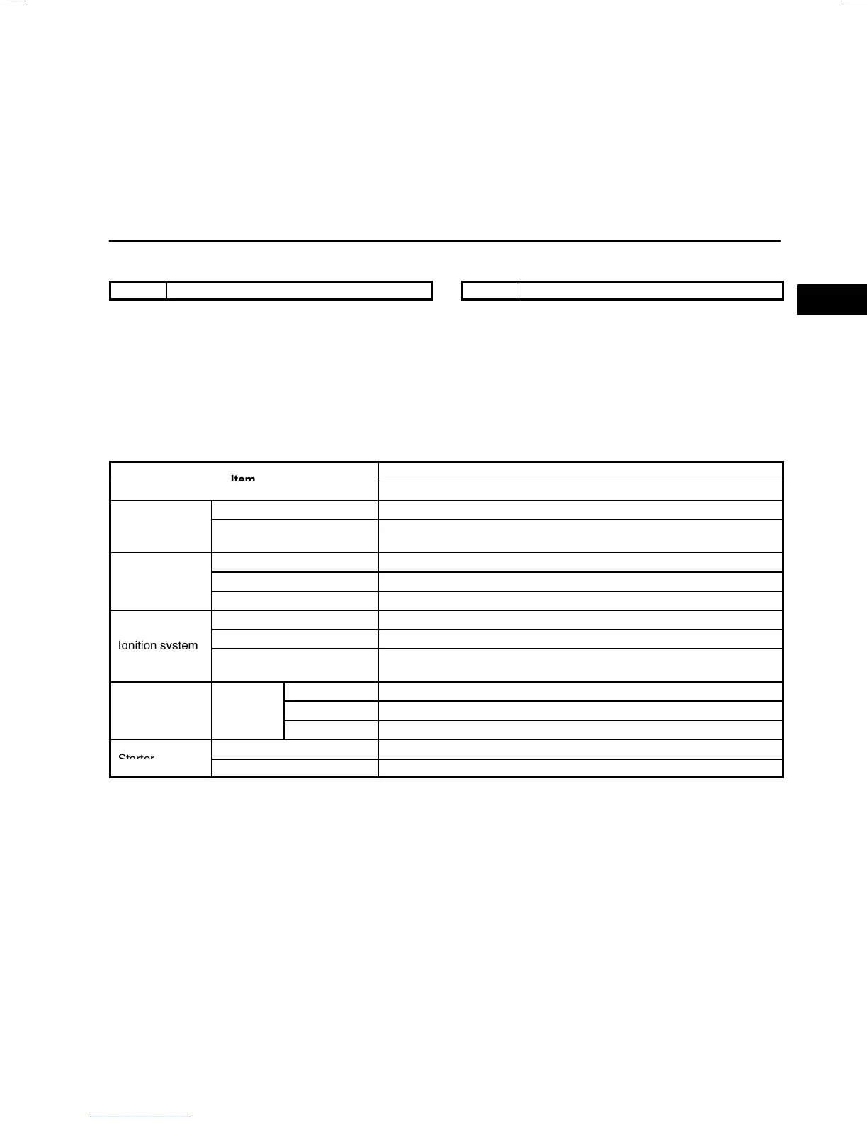
SPECIFICATIONS
Specification
FP
Voltage (V) 12
Battery
Type and capacity
(5Ćhour rate) (A·h)
50D20L (40)
Output (V-A) 12Ċ80
Generator Regulated voltage (V) Controlled by PCM
SelfĆdiagnosis function Integrated in PCM
Type DLI
Spark advance Electronic
Firing order
1Ċ3Ċ4Ċ2(1·4-3·2-4·1-2·3)
Two cylinders fire simultaneously for each.
NGK BKR5E-11
*1
, BKR6E-11
*2
Spark plug Type DENSO K16PR-U11
*1
, K20PR-U11
*2
CHAMPION RC10YC4
*3
, RC8YC4
*2
Type Coaxial reduction
r
r
Output (kW) 1.0
*1
: Standard plug
*2
: Cold type plug
*3
: Hot type plug