Task
1
Plug the cable appropriate for use with your transceiver module into one of the Monitoring ports, for
example G1/1.
2
Plug the cable appropriate for use with your transceiver module into one of the Monitoring ports, for
example G1/2.
3
Connect the other end of each cable to the network devices that you want to monitor.
For example, if you plan to monitor trac between a switch and a router, connect the cable connected to 1
to the switch and the one connected to 2 to the router.
Connect the cables for tap mode
To deploy the Sensor in tap mode, you must use a Sensor's Gigabit Ethernet Monitoring port pair with a
third-party external tap.
For a list of McAfee-approved third party vendors, see the KnowledgeBase at http://mysupport.mcafee.com/
Eservice/. Click Search the KnowledgeBase and locate the relevant KnowledgeBase article.
Task
1
Plug the cable appropriate for use with your transceiver module into one of the Monitoring ports, for
example, G1/1.
2
Plug the cable appropriate for use with your transceiver module into one of the Monitoring ports labeled
G1/2.
3
Connect the other end of each cable to the tap.
4
Connect the network devices that you want to monitor to the tap.
Connect the cables for SPAN or hub mode
For the Sensor, monitoring in SPAN or hub mode occurs in in-line fail-open mode. When you monitor in SPAN or
hub mode, you use only single ports.
To connect an Sensor to a SPAN port or hub, plug an LC ber-optic or 45 cable into one of the modules and
connect the other end of the cable to the SPAN port or the hub.
Connect the cable for Sensor failover
For Sensor failover, connect two NS-series Sensors using the appropriate cables. These two Sensors must be
running the same software version. Failover cables are the only additional hardware required to support
failover communication between two NS-series Sensors.
Refer the following table before you congure a failover pair:
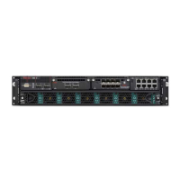
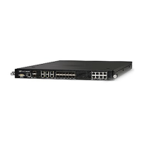
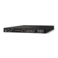
Sensor Model Port to connect the failover pair Cable requirements for failover
NS9500 G0/1 QSFP28/QSFP+ Direct Attach Copper (DAC)
The system ships with a 1m QSFP28 DAC cable. This can be used for failover connection if the failover sensors
are placed within 1m.
7
Attaching cables to the Sensor
About connecting cables to the Monitoring ports
32
McAfee Network Security Platform