The supported transceiver modules are QSFP28, QSFP+, SFP+ (MM and SM), SFP Fiber (MM and SM) and SFP
Copper.
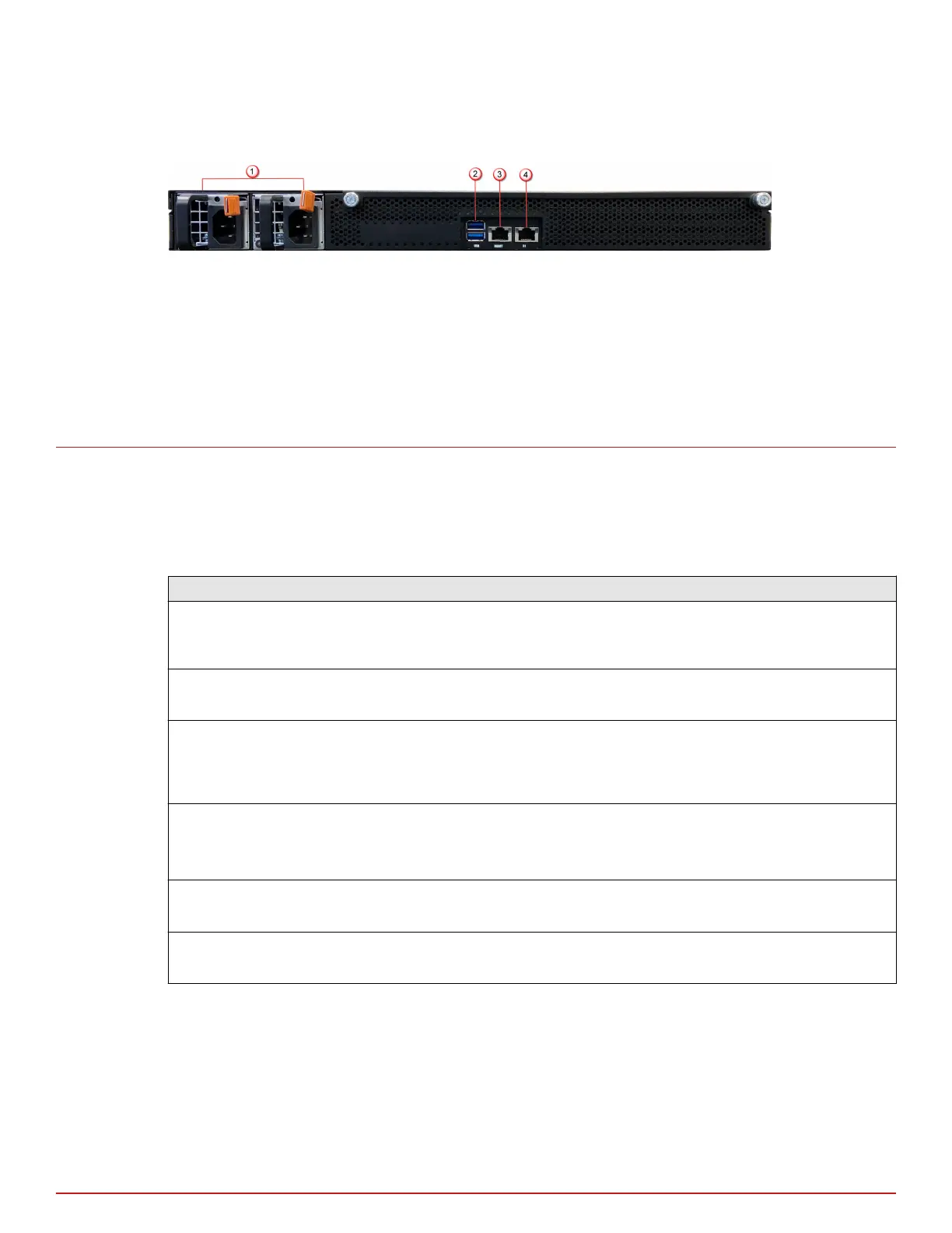
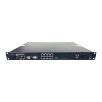
Figure 2-2 Sensor rear panel
1
Power supply A/B (Pwr A/Pwr B)
2
USB ports (2)
3
RJ-45 1000/10000 Management port (Mgmt) (1)
4
RJ-45 1000/10000 Response port (R1) (1)
Sensor LEDs
The front and rear panel LEDs provide status information for the health of the Sensor and the activity on its
ports. The following table describes the NS-series LEDs.
Front panel LEDs
LED Status Description
Status Green
Amber
Sensor is operating in good health.
Sensor is booting up. Also indicates system bad health if the LED is on for longer
duration.
Fan Green
Amber
All ve fans are operating.
One or more of the fans has failed.
Temp Green
Amber
Inlet air temperature measured inside the chassis is normal. (Chassis
temperature OK.)
Inlet air temperature measured inside the chassis is too high. (Chassis
temperature too hot.)
Gigabit Ports
Speed
Green
Amber
O
The port speed is 10000 Mbps.
The port speed is 1000 Mbps.
The port speed is 100 Mbps.
Gigabit Ports Link Green
O
The link is up.
The link is down.
RJ45 FailOpen/
Bypass
Green
O
The port pair is in Inline Fail-Open/Inline Fail-Close/Span/Tap Mode.
The Port Pair is in the Bypass Mode.
2
NS-series physical description
Sensor LEDs
8
McAfee Network Security Platform