4-11
© 2015 Mobile Climate Control
T-367 Rev. 05/2015
4.7.4 Adding Partial Charge
a. Check charge level in accordance with the p ro ce
dures of paragraph 4.7.2.
b. Install manifold gauge set at the compressor suc
tion service valve and discharge service port. See
figure Figure 4-5.
c. Place appropriate refrigerant cylinder on scale.
Prepare to charge vapor refrigerant by connectin g
charging hose from container to center connec
tion on gauge manifold. Purge air from hoses.
d. Run the unit in the cool mode for 15 minutes with
minimum of 150 psig (R134a). It may be necessary
to heat coach to provide adequate heat load. With
the suction service valve midseated, open the re
frigerant cylinder valve and add vapor charge until
the refrigerant level appears in the lower receiver
sight glass. If it is not at the proper level, add or re
move refrigerant to bring it to the proper level. Re
frigerant level should not appear in the upper sight glass, as
this would indicate an overcharge.
e. Backseat the suction service valve. Close the vapor
valve on the refrigerant cylinder and note weight.
Remove the manifold gauge set and replace all
valve caps.
4.8 CHECKING SYSTEM FOR NON-CONDENSIBLES
To check for noncondensibles, proceed as follows:
a. Stabilize system to equalize pressure between the
suction and discharge side of the system.
b. Check tem p erature at th e condenser and receiver.
c. Check pressure at the filter-drier inlet service
valve.
d. Check saturation pressure as it corresponds to the
condenser/receiver t em p erature using the Tem
perature-Pressure Chart, Table 4-3.
e. If gauge reading is 3 psig (0.20 bar) or more than
the saturation pressu re in step d, noncondensibles
are present.
f. Remove refrigerant using a refrigerant recovery
system.
g. Evacuate and dehydrate the system. Refer to para
graph 4.6.4.
h. Charge the unit. Refer to paragraph 4.7.3.
4.9 CHECKING AND REPLACING HIGH OR LOW PRES-
SURE SWITCH
WARNING
Do not use a nitrogen cylinder without a
pressure regulator
WARNING
Do not use oxygen in or near a refrigera
tion system as an explosion may occur.
a. Disconnect wiring and remove switch from unit.
All u nits are equipped with a schrader valve at the
pressure switch connections.
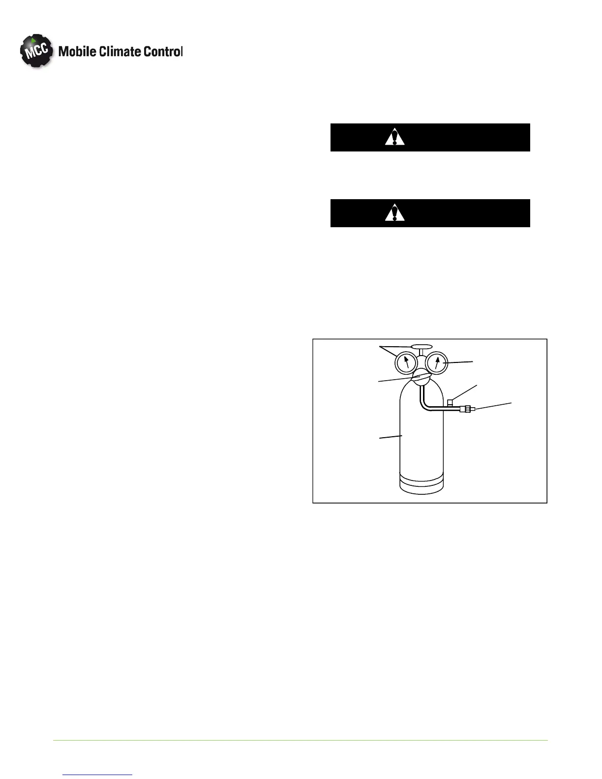
b. Con n ect swit ch to a cylin der of dry nitrogen. See
Figure 4-8.
1. Cylinder Valve and Gauge
2. Pressure Regulator
3. Nitrogen Cylinder
4. Pressure Gauge (0 to 400 psig = 0 to
27.22 bar)
5. Bleed--Off Valve
6. 1/4 inch Connection
1
2
3
4
5
6
Figure 4-8 Checking High Pressure Switch
c. Connect an ohm m eter across switch term inals.
d. Set nitrogen pressure regulator higher than the up
per switch setting. (refer to paragraph 1.3.)
e. For a high pressure switch, close cylinder valve and
open bleed-off valve. Open cylinder valve and
slowly close bleed-off valve. Th e switch should
open, (no continuity) within required cut out tol
erance. Close cylinder valve and release pressure
through the bleed-off valve. As pressure drops,