4-13
© 2015 Mobile Climate Control
T-367 Rev. 05/2015
3 Incomplete magnet circuit due to the omission of
the coil housing or plunger.
4 Mechanical interface with movement o f plunger
which may be caused by a deformed enclosing
tube.
Failure to open may be caused by the following:
1 Coil burned out or an open circuit to coil connec
tions.
2 Improper voltage.
3 Defective p lunger or deformed valve body assem
bly.
Failure to close may be caused by the following:
1 Defective p lunger or deformed valve body assem
bly.
2 Foreign material in the valve.
4.11.1 Coil Replacement
a. It is not necessary to remove the refrigerant charge
from the system.
b. Place main battery disconnect switch in OFF posi
tion and lock.
c. Disconnect wire leads to coil.
d. Remove coil retaining screw.
e. Lift coil from en closing tu b e and replace.
f. With the coil installed replace the retaining screw.
g. Connect wire leads and test operation
4.11.2 Internal Part Replacement
a. Perform a low side pump down on system. Refer
to paragraph 4.4.2.
b. Carefully loosen enclosing tube assembly and en
sure no pressure remains within the valve. Disas
semble valve and replace defective parts.
c. Assemble valve and leak check. Refer to paragraph
4.5
d. Evacuate/Dehydrate low side of system. Refer to
paragraph .
e. Op en valves and test operation..
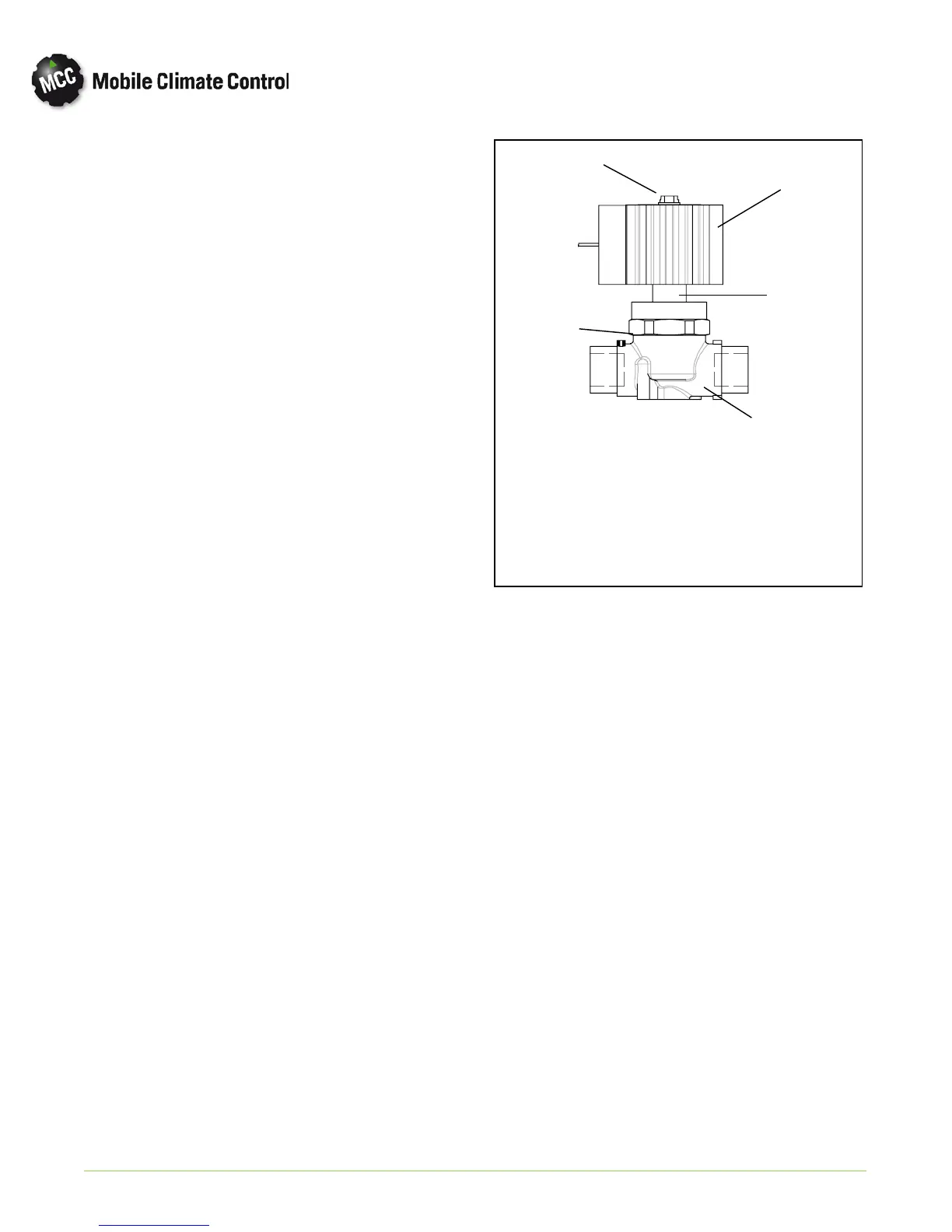
1. Coil retaining screw
2. Coil Assembly
3. Enclosing Tube
Assembly
4. Gasket
5. Body
1
2
3
4
5
Figure 4-10 Liquid Line Solenoid Valve
4.11.3 Replace Entire LLS Valve
a. Perform a low side pump down on system. Refer
to paragraph 4.4.2.
b. Remove coil assembly and enclosing tube as
sembly. Refer to paragraph 4.11.1.
c. Un-braze valve body from piping, while using an
inert gas purge to avoid system contamination
from carbon due to heat and oxidation.
d. Clean tubing to accept n ew valve b ody.
e. Disassemble enclosing tube assembly and com
ponents from new valve. Install new valve body by
brazing body to piping while using inert gas purge
to protect system contamination.
f. Once valve body has cooled, re-install enclosing
tube assembly and components on new valve.
g. Install new filter-drier.
h. Leak check connections. Refer to paragraph 4.5,
excluding th e replacement of filter drier refer
enced in step ( e ).
i. Evacuate/Dehydrate low side of system. Refer to
paragraph 4.6.
j. Replace coil assembly and test operation.