4-14
© 2015 Mobile Climate Control
T-367 Rev. 05/2015
4.12 THERMOSTATIC EXPANSION VALVE
The thermostatic expansion valve (Figure 4-10) is an
automatic device which maintains constant
superheat of the refrigerant gas leaving the
evaporator regardless of suction pressure. The valve
functions are: (a) automatic control of refrigerant
flow to match the evaporator load and (b)
prevention of liquid refrigerant entering the
compressor. Unless the valve is defective, it seldom
requires any maintenance.
4.12.1 Valve Replacement
a. Perform a low side pump down on system. Refer
to paragraph 4.4.2.
b. Remove insulation from expansion valve and
bulb.
c. Loosen retaining straps holding bulb to suction
line and detach bulb from the suction line.
d. Un-braze valve body and equalizer line from pip
ing, while using an inert gas purge to avoid system
contamination from carbon due to heat and oxida
tion.
e. Clean tub ing to accept new valve bo dy.
f. Reinstall the new valve assembly into the unit in re
verse order.
g. Leak check valve assembly. Refer to paragraph 4.5
h. The thermal bulb is installed below the center of
the suction line (four or eight o'clock position).
This area must be clean to ensure positive bulb
contact. Strap thermal bulb to suction line. Ensure
that retaining straps are tight and renew insulation.
i. Evacuate/Dehydrate system. Refer to paragraph
4.6.
j. Open isolation valves
k. Run the coach for approximately 30 minutes on
fast idle.
l. Check refrigerant level. Refer to paragraph 4.7.1.
m.Check superheat. Refer to paragraph 4.12.2.
4.12.2 Superheat Measurement
NOTE
All r eadings must be taken from the TXV
bulb location and ou t of th e direct air stream.
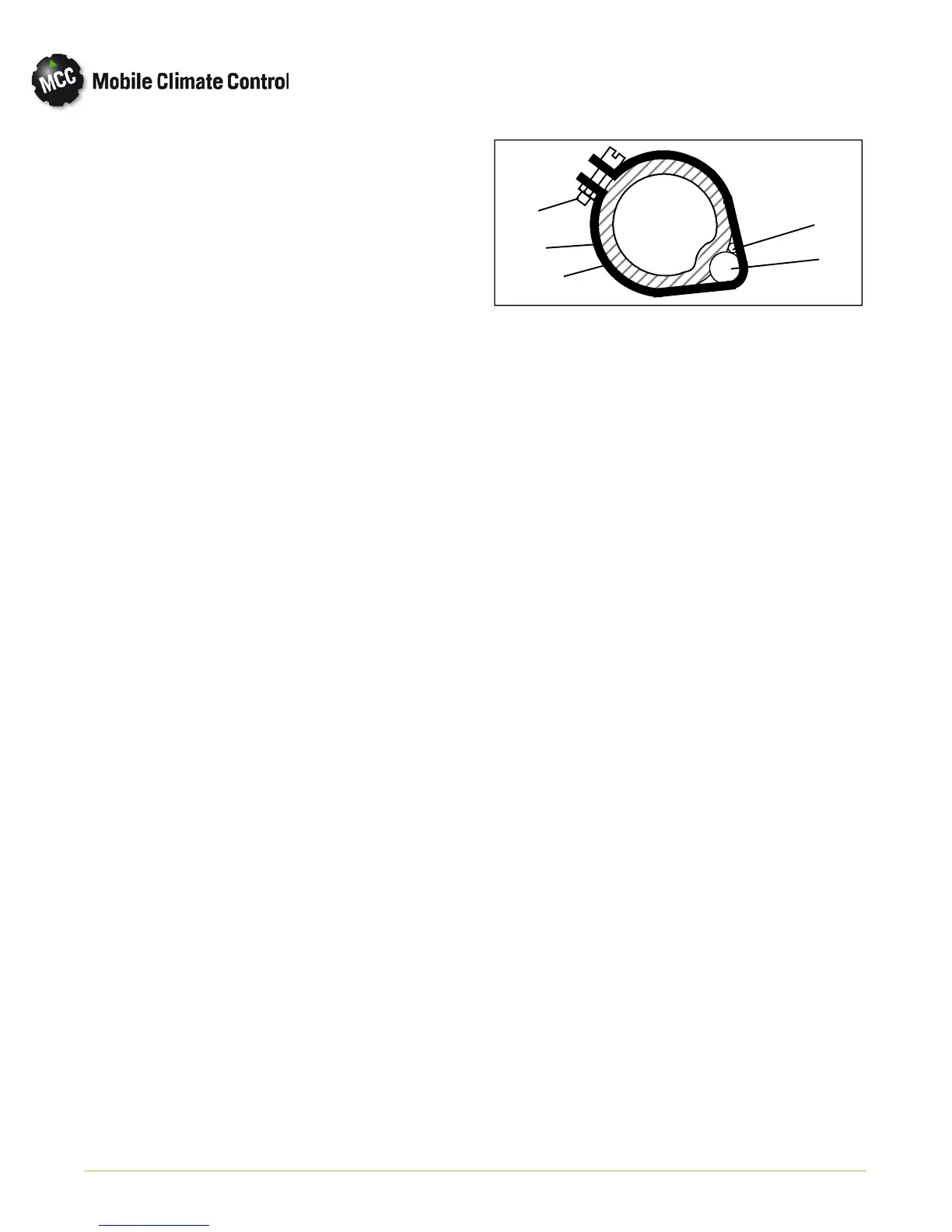
1. Suction Line
(section view)
2. TXV Bulb Clamp
3. Nut & Bolt (clamp)
4. Thermocouple
5. TXV Bulb (Shown
in the 4'clock
position)
1
2
3
4
5
Figure 4-11 Thermostatic Expansion Valve Bulb and
Thermocouple
a. Remove Presstite insulation from expansion valve
bulb and suction line.
b. Loosen one TXV bulb clamp and make sure area
under clamp is clean.
c. Place t emp erature thermo cou p le in cont act with
the suction tube and parallel to the TXV bulb, and
then secure loosened clamp making sure b o th
bulb and thermocouple are firmly secured to suc
tion line. See Figure 4-11. Reinstall insulation
around the bulb.
d. Connect an accurate low pressure gauge to the low
pressure port (Figure 1-2).
e. Start bus and run on fast idle until unit has stabi
lized, about 20 to 30 minutes.
NOTE
When conducting this test, the suction pres
sure must be at least 6 psig (0.41 bar) below
the expansion valve maximum operating
pressure (MOP) if applicable.
f. From the temperature/pressure chart (Table 4-3),
determine the saturation temperature corre
sponding to the evaporator outlet pressure.
g. Note the temperature of the suction gas at the ex
pansion valve bulb. Subtract the saturation tem
perature from this temperature. The difference is
the superheat of the suction gas.
h. The superheat m ay cycle from a low to high read
ing. Monitor the superheat taking readings every
3-5 minutes for a total of 5-6 readings. Calculate
the superheats, add the readings and divide by the
number of readings taken to determine average su
perheat. Refer to paragraph 1.3 for superheat set
ting.